Correct.
What I normally do is to connect the two heat sinks to the chassis bottom grounding point via their mounting screws. It's pretty easy to find a ring terminal that'll fit over the M4 machine screws. Double-check with an ohmmeter, but in my experience that's enough to get the chassis grounded. I guess the mounting screws for the front and rear panel wear though the anodization and provide an electrical connection.
Alternatively, sand off the anodization around the mounting holes in the panels. That'll allow them to connect to the bare metal mounting brackets for the heat sinks. Then connect the brackets to ground as described above.
Always check with an ohmmeter that the chassis is grounded. You should see less than 1 Ω between all panels.
Tom

I'd rotate the ISS 180º so the wiring to the transformer can be shortened. And rotate the transformer 180º too for the same reason. Don't forget that you need at least 10 mm standoffs on the ISS for electrical safety.
One trick I like is to mount the Guardian-86 on the heat sink, but what you have will work just fine. That works really well with the Modulus-186 and -286 as each heat sink basically becomes an amplifier + protection circuit module.
Looks good otherwise, though.
Tom
One trick I like is to mount the Guardian-86 on the heat sink, but what you have will work just fine. That works really well with the Modulus-186 and -286 as each heat sink basically becomes an amplifier + protection circuit module.
Looks good otherwise, though.
Tom
A quick question about the enclosures:
If I wanted to build something with wooden parts like the base and the front panel, do I have to worry about shielding? Would it be better to have metal panels on all 6 sides? A thin metal sheet on the inside would be easy to add to a wooden front or base. But is it necessary?
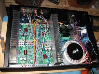
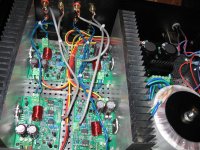
All parts have now arrived, power-86 is assembled. Just the LM3886 are not soldered yet, first I want to mount the boards onto the chassis base with the heatsinks in place to make sure they are positioned correctly.
If I wanted to build something with wooden parts like the base and the front panel, do I have to worry about shielding? Would it be better to have metal panels on all 6 sides? A thin metal sheet on the inside would be easy to add to a wooden front or base. But is it necessary?
All parts have now arrived, power-86 is assembled. Just the LM3886 are not soldered yet, first I want to mount the boards onto the chassis base with the heatsinks in place to make sure they are positioned correctly.
Attachments

Last edited:
A shielded chassis is generally preferred, both to avoid noise and RF injection but also for electrical safety. You can always line a wooden chassis with copper mesh or foil.
Tom
Tom
Gain question
Hi all,
I happily use a modulus 86 for five years...(or more😕)
I was using it with Diyinhk's differential output ES9018S DAC until recently. And the level was fairly enough for daily listening.
However when I decided to make some changes in my setup and added a Teac TN3B turntable (with 775mv line level output), I noticed that the gain/output level is not enough for this source.
So it seems I have two options to solve this problem;
1- I may change my modulus's gain to 26dB (by replacing Rf to 42K2)
2- I may add a single end input-differential output pre amp module with some gain. Like in OPA1632 datasheet page 11..
Which do you recommend? Especially for of SNR/DNR and sound colorisation etc parameters..
I doubt 26 dB will be enough. I would build a preamp with gain. My Universal Buffer or the OPA1632 circuit you mention would be good options.
Tom
Tom
If I wanted to build something with wooden parts like the base and the front panel, do I have to worry about shielding? Would it be better to have metal panels on all 6 sides? A thin metal sheet on the inside would be easy to add to a wooden front or base. But is it necessary?
I've been using aluminum roll flashing for shielding wooden enclosures (example here). Seems to work well and is inexpensive.
I'd imagine that the scrap heap at your local HVAC place would be a goldmine as well. Granted, the galvanized steel of heating ducts isn't as fun to work with as aluminum, but it can be cut with tin snips and could potentially be free.
When I was in high school and money was tight, I would often go to the local metal scrapyard/recycling place for chassis materials. That works well as long as you're willing to put in some work to get a good surface finish.
Tom
When I was in high school and money was tight, I would often go to the local metal scrapyard/recycling place for chassis materials. That works well as long as you're willing to put in some work to get a good surface finish.
Tom
I doubt 26 dB will be enough. I would build a preamp with gain. My Universal Buffer or the OPA1632 circuit you mention would be good options.
Tom
Dear Tom thanks for your reply but I meant; if I replace R14 with 42K2 (as you recommend in document) will I observe noticable changes on noise or distortion figure.
So if we consider more components = more noise / distortion on signal path and we already have enough buffer before amplifier then why should I add another buffer stage instead of a simple resistor replacing😕
You would be better off adding gain in the preamp. The reason is that if you increase the gain of the MOD86 you amplify its noise (which is ~30 dB higher than that of the Universal Buffer already). If you add a Universal Buffer (even with gain) you will not add appreciably to the output noise of the overall system because the Universal Buffer's noise is way below that of the amp.
Tom
Tom
4 CH Mod 86 finished
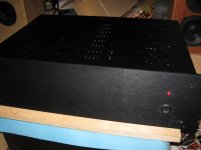
Just finished a 4 Ch Mod 86 build. Purchased an unstarted kit from another DIY member.
It sounds really sweet. I am using it with a DIY 6-24 BI amp crossover from the store and some speakers of my own design.
Just finished a 4 Ch Mod 86 build. Purchased an unstarted kit from another DIY member.
It sounds really sweet. I am using it with a DIY 6-24 BI amp crossover from the store and some speakers of my own design.
Attachments
How’d you find the 6-24 as a build project, and calculations for filter function component values?
And of course, we’ll need to know about the speakers.
And of course, we’ll need to know about the speakers.
Last edited:
The 6-24 is a straight forward build as you are mostly installing resistors and pots. My boards have not found their way into a case yet so you could say I am not done.
The calculations are easy, but not every value of cap exists so you need to model what you are buying in the XO simulator to find the pot resistance for that filter stage. Then measure the circuit to set the resistance for your starting points. Finally I used REW to measure the speakers while adjusting the filter stages. Seemed to work very well. The trick was switching from level matching pots to the filter pots when you felt like you were turning the filter pots too much. I started with 12dB slopes but then switched to 24dB slopes when I worked out the right caps.
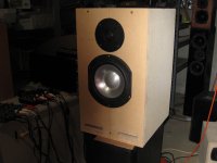
Speakers are 2 way with peerless woofer and Dayton tweeter in an 18 liter box with slot ports. If you would like to know more about the speakers I can dig up the design info.
The calculations are easy, but not every value of cap exists so you need to model what you are buying in the XO simulator to find the pot resistance for that filter stage. Then measure the circuit to set the resistance for your starting points. Finally I used REW to measure the speakers while adjusting the filter stages. Seemed to work very well. The trick was switching from level matching pots to the filter pots when you felt like you were turning the filter pots too much. I started with 12dB slopes but then switched to 24dB slopes when I worked out the right caps.
Speakers are 2 way with peerless woofer and Dayton tweeter in an 18 liter box with slot ports. If you would like to know more about the speakers I can dig up the design info.
Attachments
Nice build! It's good to see the older green boards in action. There aren't too many of those around.
Tom
Tom
Couple of questions Tom:
1. I understand that you changed the circuit a little bit , is a servo still part of the new modulus 86?
2. Are the new boards 2 or 4 layers ?
3. When I buy the boards(modulus 86) from you , am I getting the schematic ? A few years back I bought from you the modulus86 and parallel86 boards and I got the schematic for those amps.
3. I watched the video on youtube How to Build a Neurochrome Modulus-86 High-End DIY Audio Amplifier - YouTube , is that heatsink not removable ? You had to solder the lm3886 chip with no heatsink contact.
4. I would like to see the amp in and out fully assembled, is that amplifier case available for purchase ? Or at least the front/back panels ?
Thanks
You can watch the full build video here: How to Build a Neurochrome Modulus-86 High-End DIY Audio Amplifier - YouTube
"A little bit"? It was almost a complete redesign. 🙂
You can see the block diagram on the Modulus-86 product page: Modulus-86: DIY 65W power amplifier achieving – Neurochrome
Four.
No. I no longer provide the schematic. I decided to stop that when someone decided to post copies of my circuit online.
I don't understand your question. I removed the board from the chassis so I could solder the LM3886 from the bottom. I could also have removed the bottom panel of the chassis. I didn't say that my way of doing things is the only way to do things. There are many correct solutions. As long as you get the LM3886 lined up on the heat sink and the board mounted at the correct height relative to the bottom panel you'll be fine.
I would like to see that too... 🙂 That could be the topic of my next build video. I need to get some things sorted with my cameras before I can shoot that video, though.
I'm happy to sell the chassis. It's $449. That's actually below what you'd pay if you were to order one directly from the manufacturer!
Tom
1. I understand that you changed the circuit a little bit , is a servo still part of the new modulus 86?
"A little bit"? It was almost a complete redesign. 🙂
You can see the block diagram on the Modulus-86 product page: Modulus-86: DIY 65W power amplifier achieving – Neurochrome
2. Are the new boards 2 or 4 layers ?
Four.
3. When I buy the boards(modulus 86) from you , am I getting the schematic ?
No. I no longer provide the schematic. I decided to stop that when someone decided to post copies of my circuit online.
3. I watched the video on youtube How to Build a Neurochrome Modulus-86 High-End DIY Audio Amplifier - YouTube , is that heatsink not removable ? You had to solder the lm3886 chip with no heatsink contact.
I don't understand your question. I removed the board from the chassis so I could solder the LM3886 from the bottom. I could also have removed the bottom panel of the chassis. I didn't say that my way of doing things is the only way to do things. There are many correct solutions. As long as you get the LM3886 lined up on the heat sink and the board mounted at the correct height relative to the bottom panel you'll be fine.
4. I would like to see the amp in and out fully assembled, is that amplifier case available for purchase ? Or at least the front/back panels ?
I would like to see that too... 🙂 That could be the topic of my next build video. I need to get some things sorted with my cameras before I can shoot that video, though.
I'm happy to sell the chassis. It's $449. That's actually below what you'd pay if you were to order one directly from the manufacturer!
Tom
Great achievement! How do your older projects measure on the new AP, i.e. how much of the improvement in the v3 is due to improved circuit & layout and how much due to better resolution of the new AP?
It is also a great achievement considering LM4562 and LME49720 appear to be the same part, so all improvement must come from even better topology, compensation and layout!
It is also a great achievement considering LM4562 and LME49720 appear to be the same part, so all improvement must come from even better topology, compensation and layout!
I took out the THAT1200. That's the main reason the noise is lower. It wouldn't surprise me if that's the reason for the lower THD as well.
That said, some of the "improvement" certainly is from improved instrumentation. I'll measure Rev. 2.x vs Rev. 3.0 at one point. It won't be today. After working to the point of exhaustion and sleep deprivation the past week+, I will take today off.
Tom
That said, some of the "improvement" certainly is from improved instrumentation. I'll measure Rev. 2.x vs Rev. 3.0 at one point. It won't be today. After working to the point of exhaustion and sleep deprivation the past week+, I will take today off.
Tom
- Home
- Amplifiers
- Chip Amps
- Modulus-86 build thread