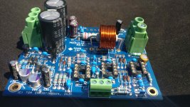
Woo hoo! Postman delivered the boards today! Let's fire up the soldering iron. Well, maybe not this week though. Work's getting in the way.
At least now that the UK is out of the EU, all of EU is now 230 V mains voltage. The UK maintained their 240 V even though everybody else harmonized to 230 V. Most of Europe used to be 220 V.
Not entirely true.
The EU, including UK, harmonised to 230V (2009?). However, tolerances were specified, in the UK they are -6%, +10% allowing voltages from around 216V to 253V (might be the same throughout EU). This meant no country needed to change immediately; you could continue to use existing plant and supply 220V or (in UK) 240V. But the plan/expectation was that new installations and upgrades/maintenance to existing installations would adopt the new 230V standard. Of course this means it will take decades to complete the transition, whether it be from 220V upwards or 240V downwards.
Europe (at least Western Europe) uses 3-phase power, so each house is fed three phases and a neutral. Lighting circuits are connected between one phase and neutral and provides 230 V. Circuits for heavier loads (washers, dryers, stoves) use the three phases with 400 V between phases. There's typically a GFCI in the panel that protects the entire house.
This still varies by country each of which has its own regulations/codes in addition to the EU harmonised rules. It is normal for a person living in one country not to know which of their rules/codes stem from the EU directives or which come from national rules. But the idea is that gradually everyone harmonises. For example, I gathered from recent exchanges that in Germany a final sub-circuit (to an appliance) is usually limited to 16A and higher power appliances would require multiple circuits (possibly different phases). This is not the case in the UK so must be a German requirement.
In the UK, whilst distribution is 3 phase, each house is fed with a single phase, live and neutral; the current standard supply is 100A but smaller properties it might be 80A. It is possible to have a 3 phase domestic supply but they are extremely rare. Capacities of final sub-circuits are not specifically constrained, but there are regulations governing cable types/sizes/lengths for given demands. As example, the circuit that supplies our cooking hob is rated at 40A and required 10mm2 conductors.
Residual Current Devices (RCDs aka GFCIs) are mandatory on all new installations (I assume a UK rule), usually multiple ones protecting groups of circuits.
Geoff
Oh, wow. It's even more of a mess than I thought.
I know in Denmark each house is fed three phases and a neutral. There's a protective earth grounding point that's usually a rod driven into the ground by the power meter. Each lighting circuit is fed from a phase (and neutral) and protected by a 16 A circuit breaker. In older installations, 10 A lighting circuits are common. The house I grew up (built in the early 70s) in had (10 A) cartridge fuses, but more modern builds have circuit breakers. It's fairly recently that they upped the lighting circuits to 16 A.
Power circuits have 16 A, three-phase breakers.
It sounds like the UK system has more in common with the North American model. I'm pretty sure the distribution here is single-phase, "medium voltage" (I forget the voltage but I think it's a few kV) to a pole transformer that steps it down to 240 VCT.
Residential lighting circuits seem to be 15 A in older builds and 20 A in more modern installations.
Tom
We seem to be way off topic. However ...
At 230V that seems high to me for a domestic lighting circuit, it's equivalent power to a 30A circuit at your 120V. That's a lot of 60W light bulbs. Here a 16A circuit would require the use of a cable with cross-section area (csa) of 2.5mm2 (~AWG13) but 10A would need a csa of 1.5mm2 (~AWG15) and 6A a csa of 1.0mm2 (~AGW17). The lighter cables are much easier to install and work with, not to say cheaper. These features more than offset the cost of an additional breaker in the consumer unit so in the UK it is common to see a small number of 6A breakers each covering the lighting of a different zone, eg different floors of the house. And, with the transition to LED lighting, the demands on the circuit are falling. Power circuits are a different story.
It was a few years ago that I realised that much of America is cabled with 240V, (much like the UK was). The significant difference being it is 'split-phase' with the 240V centre tapped with this tap grounded (at the transformer) and called neutral. So your installations can be 2 120V phases @ 180 degrees relative to this neutral; higher power devices can then use both 'hot' wires to operate at 240V. I am told that in the early 1900's some of the UK was like this but when standardisation with other regions was required, in those regions the neutral was moved from the centre tap to one of the phase conductors resulting in a single phase 240V supply.
Geoff
tomchr said:It's fairly recently that they upped the lighting circuits to 16 A.
At 230V that seems high to me for a domestic lighting circuit, it's equivalent power to a 30A circuit at your 120V. That's a lot of 60W light bulbs. Here a 16A circuit would require the use of a cable with cross-section area (csa) of 2.5mm2 (~AWG13) but 10A would need a csa of 1.5mm2 (~AWG15) and 6A a csa of 1.0mm2 (~AGW17). The lighter cables are much easier to install and work with, not to say cheaper. These features more than offset the cost of an additional breaker in the consumer unit so in the UK it is common to see a small number of 6A breakers each covering the lighting of a different zone, eg different floors of the house. And, with the transition to LED lighting, the demands on the circuit are falling. Power circuits are a different story.
tomchr said:It sounds like the UK system has more in common with the North American model. ... <snip> ... to a pole transformer that steps it down to 240 VCT.
It was a few years ago that I realised that much of America is cabled with 240V, (much like the UK was). The significant difference being it is 'split-phase' with the 240V centre tapped with this tap grounded (at the transformer) and called neutral. So your installations can be 2 120V phases @ 180 degrees relative to this neutral; higher power devices can then use both 'hot' wires to operate at 240V. I am told that in the early 1900's some of the UK was like this but when standardisation with other regions was required, in those regions the neutral was moved from the centre tap to one of the phase conductors resulting in a single phase 240V supply.
Geoff
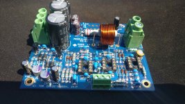
Started soldering last night and I'm really glad to have one of those bending gauges for the resistors. Making progress but unfortunately I ordered only 2 instead of 4 of the 180pF capacitors so that's going to be fun ordering more...
Another couple of questions popped up though.
Would you recommend crimping plugs to the ends of the wires or solder them directly to the terminal? My preference would be crimping but I don't have a decent tool. I'm just not so sure about soldering the mains wires to this kind of input terminal for example.
The other question is about the mains input terminals. Some of the builds in this thread are using these Schäffner input terminals/fuse holder/switch/mains filter combo parts. Is this just for convenience to have all this in one part or does it provide any further advantages? Wouldn't crimping be the preferrable solution for such connectors?
https://docs.rs-online.com/4dcd/0900766b8009bedf.pdf
Argh! $0.20 capacitors. $20 shipping. Grr! You may try Digikey (they typically charge $8 in shipping) or if you order the IEC inlet from RS anyway I'm sure you can find a 180 pF, 50 V (or higher), C0G dielectric, with 5.00 or 5.08 mm pin pitch ceramic cap there too.
The IEC inlet you show has spade terminals. I'd just crimp corresponding female spades to the internal wiring and give them a layer of heat shrink for insulation.
For the crimp tool, I recommend Molex P/N: 0640160035 (Digikey: WM17483-ND) for insulated terminals. At ~$60 it's certainly more costly than the cheap stamped sheet metal tool you'll get in a $10 terminal kit, but it's also much, much better. It's ratcheted, which makes for consistent crimps.
As my dad would say, "Buying a good tool hurts once: when you buy it. A cheap tool hurts every time you use it".
I generally recommend using fused IEC inlets for convenience. With a fused inlet you only have one hole to cut in the rear panel. There's no added wiring to worry about. So they buy safety and convenience.
Same can be said for the switched, fused, filtered inlets. The filter isn't necessary, but it doesn't hurt performance either.
Tom
No worries Tom, I totally agree that buying cheap tools usually bites you on the first use so thanks for the tip. Would these connectors be correct?
https://www.mouser.co.uk/datasheet/2/276/0190120031_QUICK_DISCONNECTS-160624.pdf
I have to order from Mouser again for the power-86 parts and with the crimping tool I'll easily get free shipping. It's just annoying to forget changing it for a single component. In the past I've ordered 3 times the parts I needed for a project because they were cheap and "just to be sure". But I still have these parts today, never needed them again so I'm trying to just buy what I need.
Making progress with the soldering but I have no idea how you can finish a board in an hour. Are you loading the board with the parts first before you solder them in one go? I followed the order from your pdf and I've been sitting there for about 3 hours for 2/3 of the components.
Yep. Those Molex spades will work as long as you're using 14-16 AWG wire. If you're using thinner wire, you'll want the red ones.
In the past I would sometimes order 10 or 100 of something even though I only needed a couple. This was mainly when I was building tube circuits. This resulted in bags of components in boxes, which I sold most of last year. Now I buy what I need. I'm not sure which approach is cheaper, but buying what I need certainly seems to result in less waste. The only exception is for SMD components where I'll often buy a couple or 10 if I need 1-2. It's just too damn easy for those parts to go *tink* off the tweezers and disappear into the air.
When I put a circuit into production I have to deliver 3-5% extra parts to the assembly house. The machine needs 3" of tape as a lead-in, so 19 parts are wasted there. Sometimes the assembly guys will get lucky and catch all of them, but they say not to count on that. So I will get bags of assorted parts back with the assembled boards. As result, I now have boxes of assorted SMD components on a few inches of cut tape. But I don't know what I have and aside from separating ceramic caps, electrolytic caps, resistors, and semiconductors I have no organization system. I strongly suspect I'll bring a box of stuff to Burning Amp at some point in the future and give it away at the raffle.
Anyway. Board assembly: I think I can actually finish two Modulus boards in an hour, or maybe 75 minutes including cleaning off the flux. It helps that I know the circuit inside out and practically have the BOM committed to memory by now. I don't have to search much to find a particular component. I know that R3 and R7 are 100 Ω and connected near the input, so my eyes go to that area of the PCB. If I'm building amp boards I nearly always build two at a time. That speeds up the process too. I find the vast majority of the time is consumed by opening the bags from Mouser, getting the parts off the tape, finding them on the BOM and the board. The soldering takes hardly any time by comparison.
I've been soldering since age 5, so for nearly 90% of my life. I know my hands and my tools well enough that I can bend resistor leads to 0.4" pin pitch by feel. So the assembly goes pretty quick.
Don't feel like you have to compete with me, though. If it takes you an evening to solder a board, so what? As long as you get all the components in the right spot and soldered well.
I start by sorting the components: Resistors, ceramic caps, power resistors, electrolytic caps, semiconductors, everything else. I hold the piles together with binder clips. I grab the first bag in the resistor pile and populate those. Then the next bag. Etc. I then mount IC sockets and diodes. Then ceramic caps. Then electrolytic caps. Then power resistors. And finally semiconductors (sans diodes).
Basically the idea is to go from the lowest to the tallest parts, from the least heat sensitive to the most heat sensitive, and from the least ESD sensitive to the most ESD sensitive. I do make an exception for the diodes. They're easier to populate while the board is relatively "flat". So they go in after the sockets even though they are more heat sensitive and more electrostatic discharge (ESD) sensitive. Discrete diodes tend to have large junctions so I'm not overly worried about zapping them with ESD, though I do take reasonable precautions.
I sometimes populate all the resistors and then solder them all, but mostly I think I solder by value. So get all 100 Ω resistors in, solder those. Then all 1 kΩ, solder those. Same for the caps.
Hope this helps.
Tom
Last edited:
Hi Tom,
thanks for the info! I'm not trying to compete, the aim is to have a working amp in the end so I spend a lot of time checking the solder spots if they are shiny and connected through to both sides. Some spots are going through to the other side and don't require soldering both sides. I'm also soldering by value. I wrote the names on the bags and go one by one. This sometimes creates little arkward spots where you don't have much space to place the tip of the soldering iron but nothing impossible.
The boards are excellent quality. On the smd boards I've soldered in the past the laquer came off in some areas which took a long time to repair if that was possible at all. Your blue boards don't seem to get a scratch. But I didn't have to use solder wick to remove solder so far, I used to get too much solder on the pins with smd stuff but here it seems to be working much better.
The best tool is the gauge for bending the resistor wires. It really helps to make the end product look more tidy.
Regards
Stefan
You don't need to solder both sides. The board is through plated. There's a sleeve of gold plated copper in each hole that connects top and bottom layers.
I use needle nose pliers for bending component leads. But the gauges can be handy too. It looks much better and probably results in less stress on the components than just jamming them in.
Tom
I use needle nose pliers for bending component leads. But the gauges can be handy too. It looks much better and probably results in less stress on the components than just jamming them in.
Tom
The board is through plated
Well, while I was wondering if that was the case I soldered it from both sides apart from the caps and the sockets where you can't reach the top side anyway. But that will help for the last few missing parts.
At least it looks pretty from both sides now....
Had one little setback, soldered U5 into the U6 position and had to remove it and move into the correct position. I hope I didn't damage it, it's taken longer than i hoped to get it removed.
I'm very limited when it comes to testing, I only have a cheap multimeter. Is there a checklist by any chance where I could follow a procedure, something like "there mustn't be connectivity between component A and component B" to check for shorts?
I'm going to check for solder bridges and anything you can see on a photo but I'd be happy to hear any tips for checking the boards before actually connecting a power supply.
There absolutely is a checklist. See page 31 of the design doc. (MOD86 Rev. 2.4) 😉
You can take it a step further by testing the ±16 V supply provided by U5 and U6 before you plug in the 8-pin ICs. I used to include this in the Final Test procedure, but it seemed to raise more questions than it was worth. Given your oopsie with U5 it's worthwhile to go through this:
Assemble the board completely but leave the three 8-pin ICs out of their sockets. If you've already stuffed those ICs I'd probably leave them in as U5 is probably OK. Or you can pry the ICs from their sockets. Just be careful not to bend their pins.
Inspect the board for solder bridges and cold solder joints. Fix as necessary. Apply ±20-30 V from a current limited power supply. Measure the voltage from pin 4 and pin 8 of U4 to ground. You should have -16 V (±1 V) on pin 4 and +16 V (±1 V) on pin 8. You should also have lowish DC offset at the output of the amp. Without the DC servo it should be below 110 mV.
If you don't have a current limited power supply, you can create one by inserting a 10 Ω, 0.25 W resistor in series with each supply lead (i.e., V+ and V-). If there's an issue with the amp those resistors will go up in smoke when you turn the power on.
If the resistors survive power-on, measure the ±16 V supply and DC offset as outlined above.
Then plug in the 8-pin ICs, remove the 10 Ω resistors on the supplies (if applicable), power up again and measure the DC offset on the amp. You should see below 1 mV. My builds typically sit around 50-100 uV. Note that to get into the uV offset levels you need to remove the flux from the board to prevent the leakage currents flowing in the flux from degrading the DC performance. You'll also likely need a bench top DMM to measure offset that low. 🙂
I generally recommend running a sine wave through the amp and measuring the gain. That's just a sanity check. You should have a gain of 10 V/V (20 dB) if the board is built according to the BOM. The design doc does list the resistor changes needed for different gains.
Tom
Last edited:
There absolutely is a checklist. See page 31 of the design doc. (MOD86 Rev. 2.4) 😉
...
Tom
Hi Tom,
I hope you're not reading this before you return from your camping trip!
You must be thinking I'm not reading the documentation but I am! The procedures described in your last post and in the documentation are a bit hardcore for me at the moment. I'm slowly beginning to understand the transformer / power supply / amp relation but there are lots of missing basics for a person who exclusively played with DC circuits in the past. I just ordered the Power-86 board and from the documentation I hope to get more info that helps me to fill some of the blanks.
I've seen some posts about limiting current with a light bulb and have to find an idiot proof procedure so connecting it to the mains won't be the last thing I do. Any device with capacitors that size require to be handled differently once charged. And my nerves are not strong enough to just discharge capacitors with a screwdriver shaft (as seen on youtube).
Stefan
I camp in areas that are outside of cellphone range, so I have no data connection. That's by design. As soon as the data connection is there, so is the temptation to check email. I find that a couple of days without internet access does wonders for my mental state.
The term Big Bang Testing often comes to mind for me when powering up an amp the first time. It's a term I borrowed from software development, where Big Bang Testing refers to writing all the code before testing it. It's a recipe for failure.
Rather, software development uses unit testing (and other methodologies). Basically, each module is tested before it's linked to the other modules and the whole system is tested.
I think we can borrow that and apply it to hardware engineering as well. Here's how:
First connect the transformer primary to the ISS (if applicable) or mains inlet. Then connect the secondary to the Power-86/686 board. Connect your power switch and standby/on indicator(s) to the ISS (if applicable). Now verify that you can turn the power on/off with the power switch. Verify that you get about ±30-32 V on the output of the power supply. The voltage will be a bit high because the supply is not loaded.
Turn the power off and wait for the power supply caps to discharge. Do *NOT* use a screwdriver to short the caps. First off, it's not necessary as there are two bleeder resistors on the Power-86/686 which will discharge the caps and, secondly, because it's really hard both on the caps and on the screwdriver. Note that you need the LED fitted on the Power-86/686 in order for the bleeders to work. If you don't like the LED, you need to connect the two terminals on the LED connector with a piece of wire to allow the bleeders to do their job.
Once the supply has discharged to below, say, ±5 V connect the amp modules. Be careful with the polarity as reverse polarity will destroy most of the silicon on the boards.
Power up again and test the DC offset and gain as outlined above.
Light bulb testers can be handy in case you have a short-circuited power supply or a mis-wired mains transformer. I personally don't use one. I just use a fused IEC inlet and rely on the fuse to do its job if I mis-wire something.
Tom
Thanks Tom, much appreciated! I wasn't so sure if I can get the inductors right so I was waiting with the power-86 order in case I have to buy a couple from you.
I'd love to get an ISS but that has to wait, I'm considering a cheap inrush limiter / soft start from Audiophonics for now or maybe just a fuse like so many of the builds here in the thread.
You've mentioned testing with a current limited power supply. Am I right to assume you meant something like a bench top power supply which provides positive and negative DC voltage and a ground?
Could you please post a link to an example? My bench power supply died recently and I'm looking for a new one anyway.
Reading the Power-86 manual now, I'm glad to see a safe discharge of the caps has been taken care of by design. This was one of my biggest concerns.
Thanks a lot Tom, I'm so glad I've started this project.
Stefan
My favourite bench-top power supply is the HP 6237B. For higher power I go for the HP 6643A.
Seriously. Get the 6237B. You won't regret it. They're available on Used-Line and similar places. If you go through eBay, make sure you get a tested one.
Tom
Seriously. Get the 6237B. You won't regret it. They're available on Used-Line and similar places. If you go through eBay, make sure you get a tested one.
Tom
I finally got all of my parts (well all but one thing, but I can start without it) and I put together my power supply today. Before I test it, I wanted to ease some of my paranoia about grounding. This is my first mains project after all.
I have an anodized black Dissipante chassis and I want to make sure I ground everything correctly. I've seen some threads around, but thought it best to double check in here. If I sand all of the joints of the chassis and check for conductivity between the sides, and top and bottom, it should be sufficient to ground all of the parts that need grounding (IEC intlet, Power 86, etc.) to the bottom of the chassis, correct?
I have an anodized black Dissipante chassis and I want to make sure I ground everything correctly. I've seen some threads around, but thought it best to double check in here. If I sand all of the joints of the chassis and check for conductivity between the sides, and top and bottom, it should be sufficient to ground all of the parts that need grounding (IEC intlet, Power 86, etc.) to the bottom of the chassis, correct?
- Home
- Amplifiers
- Chip Amps
- Modulus-86 build thread