I've often wondered about recycling Cat5... What do you do??? Strip the shielding off and break it down into the 4 pairs???
Thanks,
naa cut off a foot and grab it and pull . it comes right out of the casing !!!!
capacitance questions...
Richard-revisiting capacitance measurement of VSPS 300 inputs.
My capacitance meter measures RCA cable sensibly, almost immediately settling down to a stable and sensible pF measurement.
When I measure the either of my VSP 300s, I get a negative value that fluctuates around 100+pF, although a couple of times after a long measurement (60sec) it has jumped to 3.x or 8.xpF.
I tried this w/all opamps removed as well: same.
Is it not possible to measure with the board "loaded"?
(rhyming question: is it possible to check R values when caps are in the circuit?)
Also-what type of caps would you recommend to load the inputs?
And is there any downside to paralleling them to get desired capacitance?
Regards, Phil
As a general rule, no, you cannot measure the resistance or capacitance of components that are already soldered on to the board.
Normally no capacitance is needed on the inputs of a MM phono stage, just the 47k resistor. If your cartridge manufacturer specifies a capacitance, however, try that value. Yes, you can parallel values to get the right total.
/R
Normally no capacitance is needed on the inputs of a MM phono stage, just the 47k resistor. If your cartridge manufacturer specifies a capacitance, however, try that value. Yes, you can parallel values to get the right total.
/R
Just been playing with the second stage opamp in the Phonoclone, trying the AD797 again. This time I added 0.1uF ceramic supply bypass cap right at the power pins. That solved most of the noise issue (still more than the OPA27).
Initial thought was, wow, that bass is fuller and there's more there in the mix, however there still seems to be an element of minor distortion in the higher registers that is just not present in with the OPA27. Additionally surface noise seems slightly more pronounced. What I am really after is the dynamics, detail and bass of the AD797, with the smoothness of the upper end of the OPA27.
Considering Richards design further, it is really good. The OPA27's slew rate limits match well the 'electrolytic only' supply bypass, and the speed of the X-reg is ideally matched to the OPA27 opamps in the circuit. Basically the design is stable and uses its inherently limited bandwith to produce a very sound (sonically) output. I do wonder now if the percieved improvement in dynamics and bass with the AD797 are more related to how well the opamp drives it's load. Perhaps in this area the AD797 is superior to the OPA27?
In summary, to me the AD797 with my current layout sounds more 'hi fi', but the OPA27 makes me want to listen to music longer.
The question now is whether to persue the AD797 output stage further, perhaps ditching the opamp sockets and adding the pin 8 to output compensation capacitor, or to wait till Richards buffer boards arrive and see how these affect the game.
Decisions, decisions...
Anyone else faced this dilema?
Considering Richards design further, it is really good. The OPA27's slew rate limits match well the 'electrolytic only' supply bypass, and the speed of the X-reg is ideally matched to the OPA27 opamps in the circuit.
You noticed!
<blush>
Re. the AD797, everyone says is its a pain in the butt to work with, so your experiences fit exactly with what one might expect. Perhaps you might want to try something like the OPA134 or NE5534 as the second stage, op amps which might sound a little different but still should work fine within the framework of the Phonoclone 3 circuit without modification. If I was dead-set on getting the AD797 working, I'd build a test jig in the form of a "preamp" (volume control, 12 dB gain noninverting) or maybe a buffered headphone amp (same configuration but with an output buffer bolted on the end). I'd build it on perf board and give myself plenty of room to try different bypass cap arrangements, as well as different sources and power supplies just to make doubly sure what I was hearing was from the gain stage and not a product of the source.
Richard
PS B-boards were delivered yesterday, and look good. I will build a set over the weekend just to test the current balance, offsets and so forth, and kits will start shipping next week.
Attachments

Hi Richard,
How about the LM49710? I use it in the output stage of a samre DAC and it is very nice. Seems fairly easy to implement also, just some film caps at the supply pins.
Martin
How about the LM49710? I use it in the output stage of a samre DAC and it is very nice. Seems fairly easy to implement also, just some film caps at the supply pins.
Martin
Should work. GBWP of 55 Mhz means a bandwidth of just under 2 Mhz, so additional bypassing of the supplies is most likely required. Suggest ceramic 0.1 uF rather than film caps.
OP27 and OPA27 are functionally identical ICs from different manufacturers. Normally I use OPA27 from TI/Burr-Brown.
OPA627 is FET input design with higher bandwidth and costs $30 ea. It is not a direct substitute.
OPA627 is FET input design with higher bandwidth and costs $30 ea. It is not a direct substitute.
Pimp My Board Contest
Something for you guys who enjoy playing around in Eagle, here's a chance to show off:
RJM Audio - Pimp My Board Contest
Actually as a challenge it's fairly straightforward, so if were thinking of learning the art of circuit board design this is a good opportunity to jump in!
Something for you guys who enjoy playing around in Eagle, here's a chance to show off:
RJM Audio - Pimp My Board Contest
Actually as a challenge it's fairly straightforward, so if were thinking of learning the art of circuit board design this is a good opportunity to jump in!
From what I have read, the OPA27 is claimed by the manufacturer as being somewhat better than the original OP27, from Texas Instruments (Formerly BB) datasheet:
replacements for the industry-standard OP-27 and OP-37.
Of course, that's what they would say!
The Texas Instruments’ OPA27 and OPA37 are improved
replacements for the industry-standard OP-27 and OP-37.
Of course, that's what they would say!
Last edited:
True. That's what I meant when I said "functionally identical". Different, but not in any concrete, relevant aspect you can point to.
Something for you guys who enjoy playing around in Eagle, here's a chance to show off:
RJM Audio - Pimp My Board Contest
Actually as a challenge it's fairly straightforward, so if were thinking of learning the art of circuit board design this is a good opportunity to jump in!
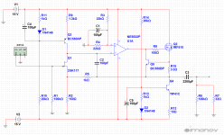
Why do you need Q2 to be BD140? You get around 17mW power dissipation on this transistor.
edit:the schematic gives an error - invalid data in file...
Last edited:

Ooh. Are you working on a layout too? I hope so!
What do R11 Q6 do? Is that your current limiter? If I'm reading it right, I suppose it is there to protect the active current source Q4 which replaces the resistor in your version.
What do R11 Q6 do? Is that your current limiter? If I'm reading it right, I suppose it is there to protect the active current source Q4 which replaces the resistor in your version.
Yes R11 and Q6 are the current limiting elements. R11 should be 3.3ohm. This gives a current limit of about 200mA. Those will protect the MOSFET from destruction when the output is shorted to ground. One should not rely on fuses here. The MOSFET will blow before the fuse.
Here is a schematic that pushes the improvement even further. The PNP transistor was replaced by an operational amplifier. This allow for achieving and extremely low THD. The opamp will allow more voltage swing at the output and the circuit can be used as a preamp. The FET load was replaced by a CCS. For lower noise the 2SK117 or 2SK170 is the better choice. For even lower noise those can be paralleled. In this case some matching is needed. All the improvements come at the cost of a split power supply.
Attachments
I received the VSPS kit yesterday. Very fast and nicely packaged.
I assembled it without problems. Only issue was that I decided to use my 15W soldering iron with a new tip I was not very familiar with, which was a problem with the micas, the transistors and the big electrolytics because the board was pulling too much heat.
I was out of flux solvent, so today I m going to buy some more to clean the boards and check them for problems.
Hopefully I m going to receive the cases, transformers and rectifying diodes from mouser today.
I promise I will post some photos very soon. Hopefully from a fully playing VSPS 🙂
I don't know how you guys manage with such low power soldering irons! Mine is variable up to 85W, and even then I find it's tough to get the solder to flow when the pads are set in the ground planes. All boards now have thermal isolation, which helps, but only a little. More heat is good, it means you can work faster and the end result is fewer fried stuff and much less frustration.
- Home
- Source & Line
- Analogue Source
- The Phonoclone and VSPS PCB Help Desk