Before I start building I have a quick R1 question
I have the kit as you supplied, and my cart is a Dynavector DV20x²L which according to the DV site has a DC resistance of 5 ohms and recommended load resistance of > 30 ohms.
Should I change R1 to 5R, leave it as the supplied kit, or ... ?
I have the kit as you supplied, and my cart is a Dynavector DV20x²L which according to the DV site has a DC resistance of 5 ohms and recommended load resistance of > 30 ohms.
Should I change R1 to 5R, leave it as the supplied kit, or ... ?
Last edited:
R1 somewhere within 4R7 ~ 10R
R2 about 150 ohms...
Your DV is one of the ones that wont work with the standard kit values unfortunately.
R2 about 150 ohms...
Your DV is one of the ones that wont work with the standard kit values unfortunately.
I just received the transformers and the cases...
OH MY it s going to be a fun evening 🙂
I just realized though... I have no idea how to drill the hammond cases to install the XLR socket... (1590DBK) 🙁
OH MY it s going to be a fun evening 🙂
I just realized though... I have no idea how to drill the hammond cases to install the XLR socket... (1590DBK) 🙁
R1 somewhere within 4R7 ~ 10R
R2 about 150 ohms...
Your DV is one of the ones that wont work with the standard kit values unfortunately.
Thanks Richard. Thought it best to check before I started burning my fingers (I mean soldering 🙄 )
I just received the transformers and the cases...
OH MY it s going to be a fun evening 🙂
I just realized though... I have no idea how to drill the hammond cases to install the XLR socket... (1590DBK) 🙁
This is how i did it....mark the place of the big hole on the Hammond case with a pencil, start drilling with a small size drill like 2 or 2.5 mm (I always start with a small size even for the smaller holes) then use a larger drill about 2 or 2.5 mm bigger as the first one, continue using a larger drill until you used your largest drill this will be a 10 or 13mm. Decrease drilling speed with increasing drill diameter and ask someone to hold the case for you. After drilling take a round file to enlarge the hole to 19 - 20mm. The material of the Hammond cases is easy to drill and file. When the large hole is ready you can mark the small holes with a pensil with the XLR connector placed in the large hole.
Succes,
Ronald.
I have this - thing - it looks like a little metal Christmas tree - that I can use to drill various sizes of hole up to 22 mm dia. or so.
Google tells me it's called a "step drill bit".
Google tells me it's called a "step drill bit".
I bought a round saw thingy that looks like a cup and fits on my drilling thingy (27mm which will give some air to the plug too). I will try this today.
I could not find a Christmas tree looking thingy 🙂
Damn different languages.... 😀
By the way, I played around with the transformers and the rest of the stuff, and everything works nicely so far.
The only problem is that the flux removal spray that I got left some serious residuals... I need to find some clear spirit...
Last edited:
Before I start building I have a quick R1 question
I have the kit as you supplied, and my cart is a Dynavector DV20x²L which according to the DV site has a DC resistance of 5 ohms and recommended load resistance of > 30 ohms.
Should I change R1 to 5R, leave it as the supplied kit, or ... ?
R1 somewhere within 4R7 ~ 10R
R2 about 150 ohms...
Your DV is one of the ones that wont work with the standard kit values unfortunately.
Sorry to be a pain, but just to check again.
My DV (being the L version) cart has an output of 0.3mV (at 1KHz, 5cm/sec.)
Putting 0.3 in the spreadsheet gives 1333r3 putting 2.8 (the output from the H version) gives 142r8
so, 150r or the supplied default?

Power Supply output is 25.6
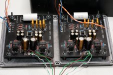
My power supply for the Phonoclone 3 reads 25.6 to 25.8 VDC. Is this correct. I am a little confused about the post about dual rectifiers and 12V secondary power supply outputs. Measuring at the + and - on each rectifier reads 12.8V. Attached is a picture of the power supply as wired. Thanks.
My power supply for the Phonoclone 3 reads 25.6 to 25.8 VDC. Is this correct. I am a little confused about the post about dual rectifiers and 12V secondary power supply outputs. Measuring at the + and - on each rectifier reads 12.8V. Attached is a picture of the power supply as wired. Thanks.
An externally hosted image should be here but it was not working when we last tested it.
Yes, that's fine. The supply output V++ V-- will measure only about 0.7 of the full DC voltage until it is connected to the filter capacitors that are on the phonoclone/vsps board.
Isn t the supplies supposed to be +12 and -12 in comparison to the common center reference? Just saying, because jcouwling says only 12 on both. Wiring seems ok though. From what I see the dark green wires seem to give the common refference on that red tape join.
By the way, drilling the aluminum case was much easier than what I was expecting...
Simple drilling bit got through it literally like butter.
Same with the circle saw bit for the xlr ... although 27mm proved to be a bit bigger than I expected. I might have to use some rubber washer or something to cover the small gap and give it a nice elegant look.
I now have to find some screws and nuts so that I can attach the components to the cases... damn local shops carry spacers but no screw sets... /sigh...
V++ to COM : 17 VDC (12 VDC with no filter caps)
V++ to COM : -17 VDC (-12 VDC with no filter caps)
V++ to V-- : 35 VDC (25 VDC with no filter caps)
V++ to COM : -17 VDC (-12 VDC with no filter caps)
V++ to V-- : 35 VDC (25 VDC with no filter caps)
Before I solder the transistors on to the board, can I check that I have the pin order correct.
Having the transistor face up (being able to read the writing) and legs towards me, I think from left to rightthe pins areE C B
Is that correct?
Having the transistor face up (being able to read the writing) and legs towards me, I think from left to rightthe pins areE C B
Is that correct?
@quan
Thanks for letting me know. Please follow the updates at the B-board thread. Drop me a line if you have questions.
@Mr. Onion
That's right, face up looking at the lettering, legs down, pin left to right are 1,2,3 or ECB. Look to match the "E" letter on the boards, or failing that note that the package outline on the silkscreen has a thick edge to denote the back side.
Excellent. Thank you Richard.
Just transistors and interconnects to go (and waiting for the case to arrive)
Just transistors and interconnects to go (and waiting for the case to arrive)
Sometimes I feel so damn stupid... or even dangerous...
I trippled checked everything, and I forgot to check the xlr socket on the phono side...
Results.... giving com to V-- and V-- to com...
Further results... the capacitors on the V-- side errupted in a squishy electrolytic fountain...

I am really frustrated right now... do you think anything else might have gone along with them?
Is it worth investigating?
Another question.
I have used this transformer
229D24 Hammond Manufacturing Power Transformers
For the dual rectifying bridge I have used 8 MUR860G
I am reading +12,8 and -12,8 as expected on the output.
The issue is that after attaching it on the hammond aluminum case, it vibrates like crazy... I hear it easily a meter away, and clearly feel the vibration when I put my hand on the case.
Any advice?
Thanks a lot.
I trippled checked everything, and I forgot to check the xlr socket on the phono side...
Results.... giving com to V-- and V-- to com...
Further results... the capacitors on the V-- side errupted in a squishy electrolytic fountain...
I am really frustrated right now... do you think anything else might have gone along with them?
Is it worth investigating?
Another question.
I have used this transformer
229D24 Hammond Manufacturing Power Transformers
For the dual rectifying bridge I have used 8 MUR860G
I am reading +12,8 and -12,8 as expected on the output.
The issue is that after attaching it on the hammond aluminum case, it vibrates like crazy... I hear it easily a meter away, and clearly feel the vibration when I put my hand on the case.
Any advice?
Thanks a lot.
Attachments
That's a shame, you had everything else all nice and working, reversing V-- and COM on the power supply is game over I'm afraid: all the electrolytic capacitors will have to be replaced because even the ones that did not burst may be damaged internally. Not just the negative side eithe: since you put V-- to com that means the positive caps all saw 35V which is above the maximum rating of 25V, so they are likely damaged also.
For the transformer vibration stop now before you hurt yourself. Leave everything unplugged and examine everything again. There's a big problem, and since this involves the AC voltage you don't want to be poking around with the power on to find out what's going on.
Either you connected the primaries in reverse phase (most likely) or if you are only using one bridge rectifier, the secondaries in reverse phase (with two bridges this error is at least avoided), or you have a closed loop of conductor passing through the center of the toroid (the end of the screw holding the transformer shorting to the lid of the case will do it).
Probably best to post some photos of the power supply here, so we can have a look.
- Home
- Source & Line
- Analogue Source
- The Phonoclone and VSPS PCB Help Desk