In the TranBal Hfe and Vbe are IMO not very relevant
True but otherwise Hfe is very important in bipolar low noise circuits, it defines the input current noise. Hfe was the beauty of the now extinct low noise bipolars like 2SC2547/2SA1085; they combined low Rbb (under 2 ohm) with very high Hfe (1000 was very common). At 15mA, this leads to 0.7pA/rtHz, while with the ZTX devices one cannot hope for anything lower than 2.5pA/rtHz. Not important for a few ohms of source impedance, but for a high level MC cartridge this could be very important in the noise budget.
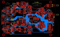
Here is the PCB so far - still some more refining to do but nearly there. board is 160mm x 110mm.
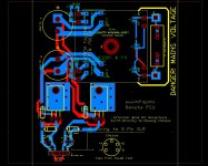
Remote +-15V PSU is also finished. After that the rear panel will be done for those that want to use a Modushop housing (through the rear panel away and use the PCB rear panel - same as X-Altra).
Remote +-15V PSU is also finished. After that the rear panel will be done for those that want to use a Modushop housing (through the rear panel away and use the PCB rear panel - same as X-Altra).
Attachments
Bonsai,
I think something slipped through your mind.
Not a serious problem because it just concerns the values of a few resistors.
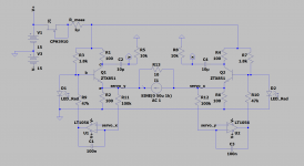
In your original design you had separate collector resistances going from 200R to 50R
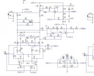
Now you have a much better solution with fixed 300R collector resistances and three partly selectable resistance values between both collectors.
These values are a bit hard to read, but they look like 220R as a fixed value and another 220R to be optionally placed in parallel and a third one of unknown value.
However since these resistors are connected to the collectors, the circuit sees a 220R as a 110R and so on.
So if you want to start with what can be compared as the former 200R collector values, the fixed 220R should be 1200R, because (1200/2)//300=200.
To get as the next step a gain as with the former 100R, you shoud place 400R in par. to the fixed 1200R while (400/2)//1200/2)//300=100, and so on.
Hans
I think something slipped through your mind.
Not a serious problem because it just concerns the values of a few resistors.
In your original design you had separate collector resistances going from 200R to 50R
Now you have a much better solution with fixed 300R collector resistances and three partly selectable resistance values between both collectors.
These values are a bit hard to read, but they look like 220R as a fixed value and another 220R to be optionally placed in parallel and a third one of unknown value.
However since these resistors are connected to the collectors, the circuit sees a 220R as a 110R and so on.
So if you want to start with what can be compared as the former 200R collector values, the fixed 220R should be 1200R, because (1200/2)//300=200.
To get as the next step a gain as with the former 100R, you shoud place 400R in par. to the fixed 1200R while (400/2)//1200/2)//300=100, and so on.
Hans
Dream on, it doesn't in real life.
Vref will be all over the place and by no way being constant with a low output Z.
BTW: you made my day.
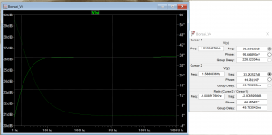
Actiually, the PSRR is much higher.
Happy to have made anyone's day:
Attachments
Bonsai,
I think something slipped through your mind.
Not a serious problem because it just concerns the values of a few resistors.
In your original design you had separate collector resistances going from 200R to 50R
Now you have a much better solution with fixed 300R collector resistances and three partly selectable resistance values between both collectors.
These values are a bit hard to read, but they look like 220R as a fixed value and another 220R to be optionally placed in parallel and a third one of unknown value.
However since these resistors are connected to the collectors, the circuit sees a 220R as a 110R and so on.
So if you want to start with what can be compared as the former 200R collector values, the fixed 220R should be 1200R, because (1200/2)//300=200.
To get as the next step a gain as with the former 100R, you shoud place 400R in par. to the fixed 1200R while (400/2)//1200/2)//300=100, and so on.
Hans
Hans, I sim'd these to get c. 5mV out at 1kHz (The output range is 3.8mV to 5mV for the carts) nominal using the lowest output and highest output carts in the table I posted a few pages back - so indeed it is not the same as the original. However, I am open to correction and/or to update the values.
(Note I have tried to minimize the spread in resistor values used - so there is quite some paralleling/series of values in general)
Attachments
Last edited:
Actiually, the PSRR is much higher.
Happy to have made anyone's day:
Is this a joke or what?

To be honest I actually expected a bit more from you Jack.
Stein
Recently, I read Bob Cordell's site about his phono pre-amplifier, but schematic did not complete. I do not want to buy his article in Linear Audio magazine. Luckily, I found LSK489 application note and I made simulation balanced MM phono with similar principle from Bob Cordell's site. With gain of 20 dB without global negative feedback, the distortion still very low.
I want to add this balanced MC phono pre-amplifier and keep the output balanced to connect to my MM phono pre-amplifier. Thank you for sharing great idea and design.
I want to add this balanced MC phono pre-amplifier and keep the output balanced to connect to my MM phono pre-amplifier. Thank you for sharing great idea and design.
Here are the Gerbers I will order boards in the next few days and once I have them, assemble the first protos. If you want to go ahead on your own at this stage, please feel free to do so, but no guarantees at this stage. It will take 14-21 days for my boards to arrive after ordering, so I don't see these being assembled and tested until before the end of January. I will in the interim also have to order the Modushop Housings.
Attachments
I have to apologize for my comment wrt the ZTX851's -- I got several quite close matches from a Mouser batch, but as I started looking for more matches and the results (Vbe) were a little more dispersed than I had hoped.
With a simple 5V supply and closely matched ZTX851's, emitter and collectors resistors, I am getting emitter voltage on both devices within a milliVolt or so. I still haven't gotten the servo to work correctly, however.
With a simple 5V supply and closely matched ZTX851's, emitter and collectors resistors, I am getting emitter voltage on both devices within a milliVolt or so. I still haven't gotten the servo to work correctly, however.
- Home
- Source & Line
- Analogue Source
- Low noise Balanced MC Pre