Eccentric discs would be modulated by the 33.33 rpm cycle or 0.55 Hz. I don't know if this is audible. The ±45 degree L, R groove modulations are orthogonal to the tangential direction, which should provide a degree of independence from tangential amplitude modulation.If you are playing a record that is off centre, an all to common occurrence, it appears that the tone arm and stylus would be oscillating in and out as the stylus is also moving side to side with each revolution. Would this cause additional pitch change as the stylus velocity is changing with the changes in tone arm length? Sort of a Doppler effect? If so, would this add to the pitch change we are already getting from the left to right movement of a conventional arm, or compensate for it? What would be the degree of this change in comparison to the existing side to side changes?
It is absolutely audible because the linear grove speed at the stylus position varies with radius; as the radius increases and decreases the pitch warbles up and down, giving a doppler like effect of coming (higher pitch) and going (lower pitch). The same happens with vertical eccentricity (wobbly platter) and warped records where the linear groove speed increases on the rises and falls going back down. Even a fraction of a mm of eccentricity is audible.Eccentric discs would be modulated by the 33.33 rpm cycle or 0.55 Hz. I don't know if this is audible.
Thanks to everyone who tried to put me straight with this design. The tonearm is tangential tracking but there will be sideforce. There is sidethrust.
Hello Bon,
Don't be discouraged. If it was easy, everyone would be doing it.
For the time being, I believe that a pivoting truly tangential tone arm that does not skate, can't be achieved without servo control. If you solve that problem, my hat will be off to you.
Sincerely,
Ralf
All of vinyl problems: off center, tracking, anti-skate, warps up and down tracking weight etc etc etc these were all addressed by Sony with their PS-X800 T/T with a tangential linear Bio-Tracer arm that had a sensors and micro motors in it for every problem above that vinyl had. Best sounding TT/arm I ever had, never had a problem over the 2 years I had mine, but many gave problems after a while.
Then along came digital.��
Sony PS-X800 on thevintageknob.org
Cheers George
Then along came digital.��
Sony PS-X800 on thevintageknob.org
Cheers George
Last edited:
A tangential tracking pivoting tonearm #10
I did not like the idea of multiple struts to cancel sidethrust. I am seeking a passive solution that addresses the issue in more direct fashion.
So I went back to the main result, the tangential stylus path and the rear end path are known exactly.
Previously the rear end path was closely approximated by a unique circle and a strut enforced the rear circular path, to give a close approximation to a tangential stylus path. I will leave this approach for the meanwhile, to engage with exact tangential tracking.
Now to look at the exact tangential paths. To enforce the rear end path, I propose a smooth cam surface of the precise profile and a guided bearing attached to the tonearm rear that follows the cam surface. Such a surface is possibly made from a low friction material by CNC router. The fabrication details will be ignored until the theoretical performance is assessed.
Assuming frictionless bearings and tangential tracking, I set out to determine the nature of the sidethrust, so as to know what I am dealing with.
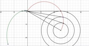
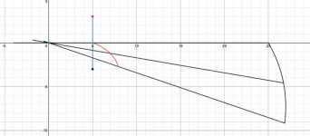
Diagram 1 shows the tangential paths for the 25 cm initial effective length tonearm. Out of interest, I have shown the rear stub path for the complete tangential stylus path from LP centre to the fixed sliding pivot (Thales semi-circle), which is off the LP surface. The relevant part of the tonearm rear stub path, lies in the 3rd quadrant. Assuming the rear stub bearing follows the smooth curve of the cam, there is a force reaction purely at 90 degrees to the curve.
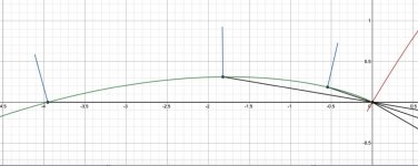
Diagram 2 is an expanded view of the rear curve, where the direction of the reaction is shown at 3 locations (outer, mid and inner grooves). The 3 short outwards lines indicate the direction of the normal line (90 degree to the tangent). This is the direction of the rear tonearm reaction force. At equilibrium (stationary in a locked centred circular groove), the reaction force component along the tone arm counters exactly the forward frictional drag. The normal component produces a torque about the horizontal pivot that is exactly balanced by the stylus sidethrust counter torque. With these 2 conditions, a formula for the stylus sidethrust emerges. If beta is the acute angle between the tonearm and the rear reaction force, F the stylus/groove frictional drag, S the stylus sidethrust, the S/F = k(r)tan(beta(r)), where r is the radial distance from the disc centre. (Sorry about the maths). The scale factor k(r) depends on the groove radius and k(0) = 0, which agrees with zero skating force at the disc centre. The actual drag force will depend on many factors (coefficient of friction, VTF, modulation level etc) but I am concerned only with the relative connection with skating force.
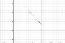
Diagram 3 shows the rear reaction force angle to the tonearm beta between the outer and inner grooves.
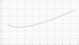
Diagram 4 shows the stylus relative skating force between the outer and inner grooves. The vertical scale is x10 to show the variation more clearly. There is approximately a 25% decrease in sideforce from the inner to outer grooves, but the minimum value shows a 30% decrease from the outer groove. A similar trend has been reported for conventional pivoted tonearms sidethrust.
https://www.audioasylum.com/images/Skating-force-Misunderstanding-and-misinformation-about-it.pdf
Now I have a handle on what needs to be compensated.
(Directdriver, please feel free to repost this with diagrams embedded for readability).
I did not like the idea of multiple struts to cancel sidethrust. I am seeking a passive solution that addresses the issue in more direct fashion.
So I went back to the main result, the tangential stylus path and the rear end path are known exactly.
Previously the rear end path was closely approximated by a unique circle and a strut enforced the rear circular path, to give a close approximation to a tangential stylus path. I will leave this approach for the meanwhile, to engage with exact tangential tracking.
Now to look at the exact tangential paths. To enforce the rear end path, I propose a smooth cam surface of the precise profile and a guided bearing attached to the tonearm rear that follows the cam surface. Such a surface is possibly made from a low friction material by CNC router. The fabrication details will be ignored until the theoretical performance is assessed.
Assuming frictionless bearings and tangential tracking, I set out to determine the nature of the sidethrust, so as to know what I am dealing with.
Diagram 1 shows the tangential paths for the 25 cm initial effective length tonearm. Out of interest, I have shown the rear stub path for the complete tangential stylus path from LP centre to the fixed sliding pivot (Thales semi-circle), which is off the LP surface. The relevant part of the tonearm rear stub path, lies in the 3rd quadrant. Assuming the rear stub bearing follows the smooth curve of the cam, there is a force reaction purely at 90 degrees to the curve.
Diagram 2 is an expanded view of the rear curve, where the direction of the reaction is shown at 3 locations (outer, mid and inner grooves). The 3 short outwards lines indicate the direction of the normal line (90 degree to the tangent). This is the direction of the rear tonearm reaction force. At equilibrium (stationary in a locked centred circular groove), the reaction force component along the tone arm counters exactly the forward frictional drag. The normal component produces a torque about the horizontal pivot that is exactly balanced by the stylus sidethrust counter torque. With these 2 conditions, a formula for the stylus sidethrust emerges. If beta is the acute angle between the tonearm and the rear reaction force, F the stylus/groove frictional drag, S the stylus sidethrust, the S/F = k(r)tan(beta(r)), where r is the radial distance from the disc centre. (Sorry about the maths). The scale factor k(r) depends on the groove radius and k(0) = 0, which agrees with zero skating force at the disc centre. The actual drag force will depend on many factors (coefficient of friction, VTF, modulation level etc) but I am concerned only with the relative connection with skating force.
Diagram 3 shows the rear reaction force angle to the tonearm beta between the outer and inner grooves.
Diagram 4 shows the stylus relative skating force between the outer and inner grooves. The vertical scale is x10 to show the variation more clearly. There is approximately a 25% decrease in sideforce from the inner to outer grooves, but the minimum value shows a 30% decrease from the outer groove. A similar trend has been reported for conventional pivoted tonearms sidethrust.
https://www.audioasylum.com/images/Skating-force-Misunderstanding-and-misinformation-about-it.pdf
Now I have a handle on what needs to be compensated.
(Directdriver, please feel free to repost this with diagrams embedded for readability).
Attachments
Last edited:
Bon: regarding the antiskating solution, you have two choices:
1. A thread-and weight antiskating device. In the basic version it gives fixed torque at the tonearm pivot. But it is possible to combine with a cam that provides variable torque as the arm moves from the outer towards the inner groove. Or make use the fact that the angle between the the rear part of the arm and the thread varies, so the orthogonal component of the pulling force changes. Place the antiskating device so that the thread is orthogonal to the arm at the outer grooves (maximum antiskating) and it is at <90° angle at the inner grooves (minimum antiskating).
2. A spring device. The spring force and the torque varies as the arm moves.
I believe the spring solution is not applicable easily to your arm, because it supposes a fixed pivot point, and yours is sliding.
Magnetic antiskating is also possible.
For example, place a horizontally-oriented bar magnet at a suitable distance from the outer part of the horizontally-rotating section of the tonearm, and wrap a variable-width belt made from a permeable material around the horizontally-rotating section. The antiskating curve is programmed into the shape of the belt - widening the belt increases antiskating forces, and narrowing the belt does the reverse.
Alternatively, the outer part of the horizontally-rotating section of the tonearm can be made as a permeable cam, with the anti-skating curve programmed into the shape - lessened distance between cam and horizontally-oriented bar magnet increases antiskating forces, and increased distance accomplishes the opposite.
Both approaches can potentially reduce noise, friction or resonances, as there are no springs, and the belt / cam pivot is the same as that required for tonearm horizontal rotation.
The underlying principles are identical as those causing torque ripple in electric motors (a.k.a. cogging), but used as a benefit instead of a hindrance.
PS. Horizontally-oriented bar magnet specified because Bon's pivot point slides as well as rotates; for non-sliding pivots a symmetrically-shaped magnet will suffice.
a new era
The above quote has haunted me for over 11 years and it doesn't seem like someone will be able to prove him wrong. I learned from Conrad early on, the hard way, in my own thread that whenever either a new product or diy project involving passive pivoting tangential tracking tonearm I always go back to Conrad's quote, sort of like Ray's string test. Ten years have passed and no one seems to be able to come up with a skate-less pivot arm.
I think we have entered a new era of invention that instead of coming up with clever tangential geometries, it is time to accept physics and put our creativity and energy into inventing an effective and accurate anti-skating device for pivoting tangential tonearm. (I do not like using the word "linear" in this genre of arms as they do not employ linear bearings nor they do parallel tracking.)
I'm less interested in a pivoting headshell these days as it places the bearing at the most sensitive area, despite the high quality bearings Thales tonearms used, as it is located right above the stylus and more importantly such pivot point is furthest away from the locus of the Thales semi-circle. A pivoting base is closer to the locus a la Birch, Schroeder LT, Reed 5A, Thiele TA01, etc..., so it should generate less skating force to begin with so that's a good starting point. 2wice and Bon's creations advanced further into that concept and we should never count out Carlo's and Doug's inventions either. Ladies and gentlemen, it is now time to come up with that holy grail . . . the most accurate anti-skating device. I look forward to such invention. Thank you for all the contributions from members I read over the years.
"If you draw a line, or at least a vertical plane, through the stylus/cartridge and it doesn't intersect the arm pivot, you've got forces you don't want."
-Conrad Hoffman in 28th April 2010
The above quote has haunted me for over 11 years and it doesn't seem like someone will be able to prove him wrong. I learned from Conrad early on, the hard way, in my own thread that whenever either a new product or diy project involving passive pivoting tangential tracking tonearm I always go back to Conrad's quote, sort of like Ray's string test. Ten years have passed and no one seems to be able to come up with a skate-less pivot arm.
I think we have entered a new era of invention that instead of coming up with clever tangential geometries, it is time to accept physics and put our creativity and energy into inventing an effective and accurate anti-skating device for pivoting tangential tonearm. (I do not like using the word "linear" in this genre of arms as they do not employ linear bearings nor they do parallel tracking.)
I'm less interested in a pivoting headshell these days as it places the bearing at the most sensitive area, despite the high quality bearings Thales tonearms used, as it is located right above the stylus and more importantly such pivot point is furthest away from the locus of the Thales semi-circle. A pivoting base is closer to the locus a la Birch, Schroeder LT, Reed 5A, Thiele TA01, etc..., so it should generate less skating force to begin with so that's a good starting point. 2wice and Bon's creations advanced further into that concept and we should never count out Carlo's and Doug's inventions either. Ladies and gentlemen, it is now time to come up with that holy grail . . . the most accurate anti-skating device. I look forward to such invention. Thank you for all the contributions from members I read over the years.
Bon: regarding the antiskating solution, you have two choices:
1. A thread-and weight antiskating device.
2. A spring device.
Hi lcsaszar.
The problem with standard antiskating devices is how to ensure they only apply force only in a normal (orthogonal) direction to the tonearm. Because the pivot is sliding any tangential component will add or subtract to the stylus friction drag. This is something not encountered with a fixed pivot.
This deserves serious investigationMagnetic antiskating is also possible.
PS. Horizontally-oriented bar magnet specified because Bon's pivot point slides as well as rotates; for non-sliding pivots a symmetrically-shaped magnet will suffice.
If it is purely a torque, this is a possibility.Constant force spring around the fixed pivot is my bet.
Thanks all, for the suggestions. It is gratifying to get sensible support from others who have a long standing interest in the problem of tangential tracking and solutions.
Can the lateral force caused by an antiskating magnet system on the pivot bearing be balanced out by employing two equal but seperate magnets diametrically opposed applying half the required rotational torque each? The angular forces will sum but shouldn't the lateral forces will cancel?
A tangential tracking pivoting tonearm #11
Two challenging issues of this design are:
1) The sliding bearing
2) Antiskate device.
I am still evaluating the antiskate solutions. I think it will require a significant amount of work to get something that is consistent with the lofty ambitions of the proposal.
I think I have a solution for a low friction sliding pivot bearing. However I am not a machinist and this is my first attempt at tonearm design. I expect to be told my solution has problems but what is a life without challenges?
There are 2 versions, one allows 3 DOF and the other, my preferred option, allows sliding and horizontal rotation, in which case the vertical rotation will be handled by a separate bearing in a supplementary armtube closer to the stylus end, similar to the Dynavector DV507.
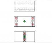
In the diagram, the upper bearing surface consists of a component fixed to the underside of the tonearm tube, with machined grooves parallel to the tonearm axis.
The lower bearing surface consists of a component fixed to the tonearm baseplate with a precision horizon bearing (green).
This bearing surface consists of either 2 grooves orthogonal to the tonearm axis (no vertical rotation) or a single groove (vertical rotation). For the 2 groove version, 4 nitride balls (red) sit in the space between the intersection of the bearing grooves.
For the single groove version (3 DOF), 2 nitride balls sit in the same space.
I anticipate the vertical load will be more than sufficient to eliminate the possibility of chatter, but I am a novice when it comes to these issues.
Comments please, especially concerning bearing materials.
Two challenging issues of this design are:
1) The sliding bearing
2) Antiskate device.
I am still evaluating the antiskate solutions. I think it will require a significant amount of work to get something that is consistent with the lofty ambitions of the proposal.
I think I have a solution for a low friction sliding pivot bearing. However I am not a machinist and this is my first attempt at tonearm design. I expect to be told my solution has problems but what is a life without challenges?
There are 2 versions, one allows 3 DOF and the other, my preferred option, allows sliding and horizontal rotation, in which case the vertical rotation will be handled by a separate bearing in a supplementary armtube closer to the stylus end, similar to the Dynavector DV507.
In the diagram, the upper bearing surface consists of a component fixed to the underside of the tonearm tube, with machined grooves parallel to the tonearm axis.
The lower bearing surface consists of a component fixed to the tonearm baseplate with a precision horizon bearing (green).
This bearing surface consists of either 2 grooves orthogonal to the tonearm axis (no vertical rotation) or a single groove (vertical rotation). For the 2 groove version, 4 nitride balls (red) sit in the space between the intersection of the bearing grooves.
For the single groove version (3 DOF), 2 nitride balls sit in the same space.
I anticipate the vertical load will be more than sufficient to eliminate the possibility of chatter, but I am a novice when it comes to these issues.
Comments please, especially concerning bearing materials.
Attachments
Another wildcard thought: have you considered the possibility of magnetic levitation used in a similar way to air suspension. Clearaudio has pivoting tonearms with magnetic levitation bearings, although those arms seem to introduce another layer of problems, including 'azimuth wobble'.
Can the lateral force caused by an antiskating magnet system on the pivot bearing be balanced out by employing two equal but seperate magnets diametrically opposed applying half the required rotational torque each? The angular forces will sum but shouldn't the lateral forces will cancel?
I can't see any reason why this wouldn't work.
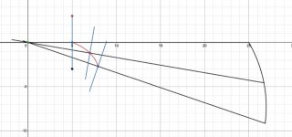
In the diagram, 2 identical magnets on a transverse strut attached orthogonal to the tonearm. Polarities opposed, but axes directed towards the fixed pillar at the origin, where is fixed another magnet with axis along the tonearm. Then the resultant force will always be orthogonal to the tonearm and directed outwards. I have shown the path of the magnet strut point of attachment. The pillar magnet at the origin rotates horizontally with the sliding bearing pivot but is not attached to the tonearm. I am sure someone with sailboat experience can put me right, one way or the other.
As the distance from the pillar magnet increases as the attachment point travels the red path, the antiskate decreases as it is supposed to. Maybe there is an optimum attachment point and strut length.
Attachments
The above quote has haunted me for over 11 years and it doesn't seem like someone will be able to prove him wrong. I learned from Conrad early on, the hard way, in my own thread that whenever either a new product or diy project involving passive pivoting tangential tracking tonearm I always go back to Conrad's quote, sort of like Ray's string test. Ten years have passed and no one seems to be able to come up with a skate-less pivot arm.
I think we have entered a new era of invention that instead of coming up with clever tangential geometries, it is time to accept physics and put our creativity and energy into inventing an effective and accurate anti-skating device for pivoting tangential tonearm. (I do not like using the word "linear" in this genre of arms as they do not employ linear bearings nor they do parallel tracking.)
I'm less interested in a pivoting headshell these days as it places the bearing at the most sensitive area, despite the high quality bearings Thales tonearms used, as it is located right above the stylus and more importantly such pivot point is furthest away from the locus of the Thales semi-circle. A pivoting base is closer to the locus a la Birch, Schroeder LT, Reed 5A, Thiele TA01, etc..., so it should generate less skating force to begin with so that's a good starting point. 2wice and Bon's creations advanced further into that concept and we should never count out Carlo's and Doug's inventions either. Ladies and gentlemen, it is now time to come up with that holy grail . . . the most accurate anti-skating device. I look forward to such invention. Thank you for all the contributions from members I read over the years.
Although I can’t say enough praises about his protractor, I respectfully disagree Conrad’s opinion.
First of all, let’s take a look of Wally Tool’s skating test video. I did the same test before but I can’t find the video now.
Skating Study (Part 5 of 6) - Overhang 2 - YouTube
In the video, the arm has off set and underhang but it doesn’t skate because the stylus is exactly on the Thales circle as I called it in my previous post. In other words even the line through the cartridge doesn’t intersect the pivot, the arm may not skate. So the off set angle is irrelevant to skating.
My argument can be applied to so called the string test as well. I don’t think the string test is useful for concluding if an arm skates.
The problem with Conrad’s statement is that he completely disregarded the interactions between arm and record. So is the string test.
Last edited:
First of all, let take a look of Wally Tool’s skating test video. I did the same test before but I can’t find the video now.
In the video, the arm has off set and underhang but it doesn’t skate because the stylus is exactly on the Thales circle as I called it in my previous post. In other words even the line through the cartridge doesn’t intersect the pivot, the arm may not skate. So the off set angle is irrelevant to skating.
My argument can be applied to so called the string test as well. I don’t think the string test is useful for concluding if an arm skates.
The problem with Conrad’s statement is that he completely disregarded the interactions between arm and record. So is the string test.
You cannot move the mounting position to simulate overhang, because of the changing geometry.
All the video proves is effective length tangency determines skate, not overhang, he's proving the string test for us.
My argument can be applied to so called the string test as well. I don’t think the string test is useful for concluding if an arm skates.
The problem with Conrad’s statement is that he completely disregarded the interactions between arm and record. So is the string test.
I also have reservations about the relevance based on my crude but illuminating experiments with the working model. If my observation that the behaviour with the roller "stylus" behaves identically to a pure frictional contact is accepted, then my experiences are still puzzling to reconcile with some of what has been stated in this thread as gospel.
Firstly, sidethrust is not always inwards regardless of where a strut may be positioned. In the video below, there is clear evidence of bi-directional skating force depending on the stylus position relative to the tangential Thales path. The direction of skating is unmistakably felt when lowering the tonearm. It consistently grabs the tonearm in an inward or outward direction depending on lowered position. It then stabilises at a position on the Thales path. This is my first hand experience of skating force interaction with an actual disc.
It is not my intention to promote disagreement for its own sake, but we should all reflect on what we hold to be inalienable truth. That is the way to progress.
Tonearm skating #4 - YouTube
Last edited:
there is clear evidence of bi-directional skating force
Because you changed the effective length vector.
You cannot move the mounting position to simulate overhang, because of the changing geometry.
All the video proves is effective length tangency determines skate, not overhang, he's proving the string test for us.
First I don’t see why I can’t move the mounting position. In my tests, I changed effective length not the mounting position. The results were exactly the same. Both of the arms in my tests and in Wally Tool’s had off-set angles. Both my arm and Wally Tool’s arm didn’t skate exactly on the Thales circle. But the line through the cartridge doesn’t intersect the pivot and it will fail the string test, too, since the arms had off set angles.
Let’s imagine an arm which is based on Birch geometry and its effective length does change. The path of the stylus is exactly the same as the Thales circle. The arm won’t skate although it doesn’t meet Conrad’s condition and fails the string test.
Last edited:
- Home
- Source & Line
- Analogue Source
- A tangential tracking pivoting tonearm