A tangential tracking pivoting tonearm #8
I would like to explain how I got here.
I have a number of excellent turntable rigs. They are based on the Technics SP10 mk2, that I have used in some form since 1998. The best sounding by far, has a Kaneta style bentonite/resin plinth and a custom POM platter.
Descriptions of the upgrades can be found here.
https://www.diyaudio.com/forums/ana...le-technics-sp-10-thread-132.html#post5959675
https://www.diyaudio.com/forums/ana...le-technics-sp-10-thread-185.html#post6671210
I am now at a stage where I am thinking about where any improvements could possibly come from. Unpleasant thought that it was, I had to acknowledge that my conventional tonearms, as good as they are, were possibly the biggest source of inaccuracy in retrieving the groove modulation. Just to be clear, I am talking of serious tonearms, SME IV, SME V12. Even the best available alternative pivoting tonearms (SAT), have the inherent limitation of the format, lateral tracking error, sidethrust compensation, as well as being insanely expensive, and out of the question price wise.
I have been employed in academic applied maths for most of my adult life. So out came the exercise book and pen, and I approached the question of how to achieve a pivoting tangential tracking tonearm from scratch. I have not knowingly followed other approaches, Posts ##1, 2, 58, summarise my reasoning. The calculations were tricky but did not used advanced maths, only trigonometry, geometry, algebra and a little complex numbers is useful. In fact using my descriptions in post #58 (thank you directdriver!) an entirely geometric compass and straight edge construction of Diagram 1 is possible. Dead on precision however, requires the maths.
The results are as presented. To my knowledge, there is no other thread that has included the detail and demonstrations that I have. I am not selling anything, or protecting intellectual property, as others have done. The only production I am contemplating is for personal use, in the spirit of DIY Audio.
If the principles can be implemented properly, there will be a minimum 3-fold reduction in tracking error compared to a conventional 12” tonearm. I don’t know how much reduction in distortion this will lead to, but I assume it will be of the same order. Will it be audible? Well the popularity of parallel tracking tonearms suggest the goal is worthwhile, even for significant cost and inconvenience.
I will soldier on till "Glory or death".
Last edited:
A tangential tracking pivoting tonearm #9
In this latest video, the tonearm is placed near the mid-groove. Speed was set to 78 rpm to speed up the movie. There is a perpendicular line across the headshell that indicates the stylus position. When it points directly at the LP centre, the tonearm is tangential. I allow the tonearm to track towards the label while watching this line. It stays on line until the run-out groove. I stop the TT there because who what happens in the run-out groove is irrelevant, they are no longer approx circles, but spirals.
There is not much else I can do to validate the concept.
BTW, I did check at 33.33 rpm and 45 rpm, with identical results. Everything just takes much longer.
Onwards to prototyping.
Tonearm cartridge in groove - YouTube
Bon,
I have no doubt that the geometry of your arm is correct and works. Your geometry is actually a variant of Birch geometry. But if you want the arm to work in reality, you need a mechanism to ensure that all the locations of the stylus are on the Thales circle as I call it before. Once you add such a mechanism, things may get complicated.
Jim
In this latest video, the tonearm is placed near the mid-groove. Speed was set to 78 rpm to speed up the movie. There is a perpendicular line across the headshell that indicates the stylus position. When it points directly at the LP centre, the tonearm is tangential. I allow the tonearm to track towards the label while watching this line. It stays on line until the run-out groove. I stop the TT there because who what happens in the run-out groove is irrelevant, they are no longer approx circles, but spirals.
There is not much else I can do to validate the concept.
BTW, I did check at 33.33 rpm and 45 rpm, with identical results. Everything just takes much longer.
Onwards to prototyping.
Tonearm cartridge in groove - YouTube
To my knowledge, there is no other thread that has included the detail and demonstrations that I have.
1005
1615
1404
1396
1119
1448
Film a string test.
Not only will it show you it's purpose, but also reveal your horizontal pivot.
Hint
Diagram 1, in the 4th quadrant is the fixed location of a horizontal bearing.
My apologies. I was ignorant of your posts. You have done a tremendous amount of work. I will look carefully at them. Can you narrow it down for me, which post will most clearly indicate why you are skeptical of my solution?
Do a string test.
I found a description of the string test here
https://www.diyaudio.com/forums/ana...tangential-pivot-tonearms-95.html#post4285998
Take a string 12” or longer, it doesn’t really matter, and tie it to the headshell or the cartridge body so that it stretches straight out from the cartridge and in line with the stylus. Balance the arm for zero VTF and let it float above the record surface. Now, gently pull on the string along the axis of the cartridge and in line with the stylus. In a true linear tracker, the arm will stay put as the string becomes taut. In a conventional pivoted arm, the arm will veer towards the spindle as the string becomes taut. With a multiple linkage design arm, if the arm veers in either direction over any tested area of the record surface, then it is susceptible to skating effects induced by stylus drag, at that tested area.
The issue is my arm will never remain floating as the headshell is tugged even infinitesimally. The tonearm is designed to lengthen as it moves inward and forward along a groove. It will attempt to fall immediately which I presume will invalidate the test.
No it won't, it is not the floating you have to worry about, you are not testing the vertical pivot, just pull.
Your arm will veer left, because your fixed horizontal pivot is to the left of your stylus vector.
If this is the result, it means there will be a skate force in this geometry.
This is not something I figured out myself, but Ray in DD's gargantuan thread taught well.
You can also attach an arm to the fixed horizontal pivot that is shorter than the horizontal pivot to spindle distance and do the string test, that one will have a zero skate force condition on the record, but at only one place.
Cart is not needed for the test.
If you look at Mr. Schröder's LT patent it has a similar geometry to your and my geometry, and his tonearm has skate, I think he used a very clever way to add counter torque to the tonearm. I'm going to use the same method as there is no extra hardware required.
I've been pleading for more people to attempt designing/building PLTs for years, so I'm very reluctant to cast doubt on anybody's efforts, but I think I see one or two snags in Bon's arm.
There have been several designs based on an over-reliance on stylus drag and a misunderstanding of the importance of side force on the stylus and the consequences for bearing type and placement. Both Carlo (nocdplz) and I found that stylus drag force by itself is inadequate to overcome typical arm effective mass and real world bearing friction.
Despite that caveat, I'd like to see Bon's design developed and I suggest a more refined working model because all sorts of things will become apparent.
One thing that gets forgotten frequently when arms first get drawn is where to park it on the TT. It helps to start with the arm drawn at its resting position rather than at the outer grooves.
If a few of this design's components are shifted around a bit, Bon has a working Birch/Thales arm.
This was a beauty.
https://i.pinimg.com/originals/fa/61/a8/fa61a8f131aff267ac79fbac1e30f188.jpg
Cheers George
https://i.pinimg.com/originals/fa/61/a8/fa61a8f131aff267ac79fbac1e30f188.jpg
Cheers George
This one wasn't:This was a beauty.
An externally hosted image should be here but it was not working when we last tested it.
Now I see it.
I should have taken more attention to my own observation
I agree now.
Thanks to everyone who tried to put me straight with this design. The tonearm is tangential tracking but there will be sideforce.
I made a relevant observation early on but did not follow through on the consequences.
Assume the stylus tracking tangentially in a circular locked groove.
If the stylus does not move, the linear forces and torques must balance.
Assuming frictionless bearings, resolving forces along the tonearm, the stylus frictional drag on the tonearm must be balanced by the component in the tonearm direction of the reaction at the rear pivot.
This means the rear strut must be in compression. Then the component at 90 degrees must impart a clockwise torque about the stationary frictionless pivot at the origin.
This torque can only be balanced by a counter torque at the stylus. The groove must be pushing on the stylus at 90 degrees to the cantilever. There is sidethrust.
I now see where the complexity arises in other tangential tracking pivoting designs.
Friction is not the only force at play here. If you do a force analysis of the tonearm at equilibrium, there will be a stylus frictional force in the forward tonearm direction. Assume that the sliding pivot is frictionless, for the sake of demonstration, as are the rear strut pivots. There will be a reaction force at the rear tonearm pivot, with a component directed towards the rear (the strut will be in compression).
There will also be a reaction component at right angles to the tonearm rear. This will be in opposition to the horizontal reaction force at the frictionless sliding pivot.
I should have taken more attention to my own observation
Hello Bon,
Any tone arm that incorporates cams, links and levers to the LEFT of its pivot, will be subject to the inward force.
Ralf
I agree now.
Thanks to everyone who tried to put me straight with this design. The tonearm is tangential tracking but there will be sideforce.
I made a relevant observation early on but did not follow through on the consequences.
Assume the stylus tracking tangentially in a circular locked groove.
If the stylus does not move, the linear forces and torques must balance.
Assuming frictionless bearings, resolving forces along the tonearm, the stylus frictional drag on the tonearm must be balanced by the component in the tonearm direction of the reaction at the rear pivot.
This means the rear strut must be in compression. Then the component at 90 degrees must impart a clockwise torque about the stationary frictionless pivot at the origin.
This torque can only be balanced by a counter torque at the stylus. The groove must be pushing on the stylus at 90 degrees to the cantilever. There is sidethrust.
I now see where the complexity arises in other tangential tracking pivoting designs.
Attachments
Where to now?
Not totally ready to give up yet.
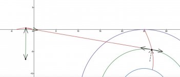
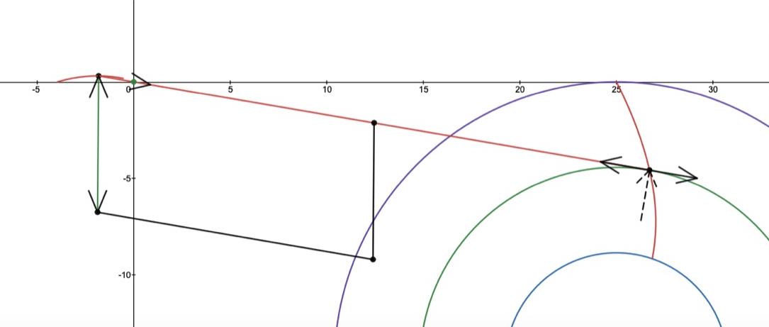
The geometry does give tangential tracking and the obvious measure to counter antiskating force is to provide a counter torque. My goal is a passive solution, so I will investigate an articulated tonearm strut connecting in front of the sliding pivot. I have added the linkage to my previous diagram. For purely reasons of aesthetics and simpler analysis, the new strut is attached to the tonearm mid point, to form a parallelogram. This reduces the number of variables substantially compared to an arbitrary linkage arrangement.
Firstly I intend to model and analyse the skating force for the original configuration, to have an idea of the varying nature of the sideforce. Then I will investigate the effect of the antiskating linkage. Even with the simplifying parallelogram arrangement, there are a number of parameters that can be adjusted to see if there is any possibility of (close to) perfect antiskate or a "sweet spot". The adjustable parameters include the tonearm original effective length and the subsequent attachment point for the linkage.
My original intention was to investigate whether tangential tracking can be achieved by a passive tonearm which does not resemble a Rube Goldberg machine. It is now looking increasingly unlikely. However, I am up for the challenge to see how close I can get, even if only as a concept. The increasing number of low-friction dependent linkage points is an obvious issue.
I did own 2 Garrard Zero 100 turntables for a short time in around 1970. They were purchased new, and at the time I was very excited with my first one. I was in college at the time and had a very modest system. Why did I have 2? Well the first one had such bad rumble I thought it must be faulty. I bought a second one, which was just as bad. A fancy tonearm could not compensate for typical cheap idler drive system.
Not totally ready to give up yet.
The geometry does give tangential tracking and the obvious measure to counter antiskating force is to provide a counter torque. My goal is a passive solution, so I will investigate an articulated tonearm strut connecting in front of the sliding pivot. I have added the linkage to my previous diagram. For purely reasons of aesthetics and simpler analysis, the new strut is attached to the tonearm mid point, to form a parallelogram. This reduces the number of variables substantially compared to an arbitrary linkage arrangement.
Firstly I intend to model and analyse the skating force for the original configuration, to have an idea of the varying nature of the sideforce. Then I will investigate the effect of the antiskating linkage. Even with the simplifying parallelogram arrangement, there are a number of parameters that can be adjusted to see if there is any possibility of (close to) perfect antiskate or a "sweet spot". The adjustable parameters include the tonearm original effective length and the subsequent attachment point for the linkage.
My original intention was to investigate whether tangential tracking can be achieved by a passive tonearm which does not resemble a Rube Goldberg machine. It is now looking increasingly unlikely. However, I am up for the challenge to see how close I can get, even if only as a concept. The increasing number of low-friction dependent linkage points is an obvious issue.
I did own 2 Garrard Zero 100 turntables for a short time in around 1970. They were purchased new, and at the time I was very excited with my first one. I was in college at the time and had a very modest system. Why did I have 2? Well the first one had such bad rumble I thought it must be faulty. I bought a second one, which was just as bad. A fancy tonearm could not compensate for typical cheap idler drive system.
Attachments
My goal is a passive solution, so I will investigate an articulated tonearm strut connecting in front of the sliding pivot. I have added the linkage to my previous diagram. For purely reasons of aesthetics and simpler analysis, the new strut is attached to the tonearm mid point, to form a parallelogram. This reduces the number of variables substantially compared to an arbitrary linkage arrangement.
Reminds me of the Thiele TA01 tonearm.

Hi folks. Great thread here and when reading it over I had a thought on the tone arm length changing in order to find tangency.
If you are playing a record that is off centre, an all to common occurrence, it appears that the tone arm and stylus would be oscillating in and out as the stylus is also moving side to side with each revolution. Would this cause additional pitch change as the stylus velocity is changing with the changes in tone arm length? Sort of a Doppler effect? If so, would this add to the pitch change we are already getting from the left to right movement of a conventional arm, or compensate for it? What would be the degree of this change in comparison to the existing side to side changes?
Thank you. I am really enjoying this respectful discussion where the magic of math is shown for use in solving a practical problem.
Bon,
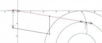
The added arm is a good idea, but it will need to be pivoted something like the arrow added to your drawing in order to accommodate the arm movement across the record and the resulting side forces. It needs to be able to collapse forward.
One way to solve the Eff Length, Eff Mass, VTF problem would be to split two functions. Pivot a rail from the horizontal bearing that will carry the linear slider and mount the vertical bearings and the rest of the arm on the slider, either above or below. The new stub you added can be used to keep the vertical bearing housing vertical.
Unfortunately, bearings, mass and complication are added.
You and 2wice have come at PLT design from highly mathematical directions and, from a couple of his recent posts over at Angling For 90 degrees, he has developed a working design. I hope your attempt is successful, too.
Attachments
Lets face it though, get the angles perfect all the way across the record, thumbs up for that.
But you still got the big problem on at best channel separation of 30-40db at 1khz, 20db in the highs and almost 0db in the bass.
The one to figure that one out will make a fortune, then it will sound like the master tape being played, it's in the record grove, but the cartridge stuffs it up separating it and getting it out.
Cheers George
Last edited:
Bon,
The added arm is a good idea, but it will need to be pivoted something like the arrow added to your drawing in order to accommodate the arm movement across the record and the resulting side forces. It needs to be able to collapse forward.
One way to solve the Eff Length, Eff Mass, VTF problem would be to split two functions. Pivot a rail from the horizontal bearing that will carry the linear slider and mount the vertical bearings and the rest of the arm on the slider, either above or below. The new stub you added can be used to keep the vertical bearing housing vertical.
Unfortunately, bearings, mass and complication are added.
You and 2wice have come at PLT design from highly mathematical directions and, from a couple of his recent posts over at Angling For 90 degrees, he has developed a working design. I hope your attempt is successful, too.
Thanks for the encouragement Doug.
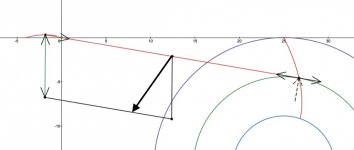
I had come to all the same conclusions as you. The sidethrust cancelling strut needs to always have a forward component along the tonearm as well as the outward component for sidethrust cancelling. Aesthetics should not come into consideration until the full picture is known.
I intend to present all of my results in such a way that others can check them if they choose. First task is to model the side thrust for the uncorrected tonearm.
Then analyse the effect of an articulated strut with arbitrary lengths and location on the tonearm. A many variable optimisation may reveal appropriate set of parameters. That's the program anyway.
If you are playing a record that is off centre, an all to common occurrence, it appears that the tone arm and stylus would be oscillating in and out as the stylus is also moving side to side with each revolution. Would this cause additional pitch change as the stylus velocity is changing with the changes in tone arm length?
Warped records, platters with horizontal or vertical runout and eccentric records all cause significant pitch variations with both linear tracking and pivoting tonearms. Doppler effect is a good way of describing the resultant sound as it seems to 'come and go'. The main way of mitigating pitch variations is lengthening the tonearm; linear tracking arms are at a disadvantage here.
- Home
- Source & Line
- Analogue Source
- A tangential tracking pivoting tonearm