Look at the videos from #28. They show skate force is zero at the null points with the anti-skate disabled. There is even a video of outward skating for underhang as in my videos. This shows that anti skate devices are compromised and possibly why a well known vinyl test LP has the bias setting tracks at the outer, middle and inner grooves, which is where most conventionally aligned tonearms have maximum skating force.Are you saying all pivoting, offset tonearms will stop on the null points? If so, which one, and what happens to the skate force at the null points?
Are you saying all pivoting, offset tonearms will stop on the null points? If so, which one, and what happens to the skate force at the null points?
Skating force is caused by overhang not headshell offset.
Skating Study (Part 6 of 6) - Overhang 3 - YouTube
A tangential tracking pivoting tonearm #7
One last video showing all the possible configurations of the working model. I now have access to a webcam so video quality is better than before. Having tested the seized roller contact and found no significant departure from the rolling contact, I used the rolling again for a number of practical reasons.
1. The seized roller was scratching up my acrylic test disc and carbon fibre mat. (You can see this in the video)
2. The noise was pretty annoying.
When the front roller is placed on the tangential path, it stayed there.
When it is displaced a small distance to an overhang position, it skates inward until it becomes tangential again and the stops skating.
When it is displaced a small distance to an underhang position, it skates outward until it becomes tangential again and stops skating.
This process was repeated consistently a number of times.
Enough with the demonstrations. Time to get on with a prototype.
Just a mention that the correct configuration is unlikely to be discovered by random experimentation. The power and beauty of mathematics showed what is required and the working model validates the mathematics exactly, so far. No fudge factors were needed.
Engineering is another matter entirely.
Tonearm skating #4 - YouTube
Look at the videos from #28. They show skate force is zero at the null points with the anti-skate disabled. There is even a video of outward skating for underhang as in my videos. This shows that anti skate devices are compromised and possibly why a well known vinyl test LP has the bias setting tracks at the outer, middle and inner grooves, which is where most conventionally aligned tonearms have maximum skating force.
This does not seem correct, the null points are not related to the skate force at all, they only indicate where the stylus is tangential to the spindle.
There should still be skate force at the null points because the error comes from the horizontal pivot to stylus vector not being tangential to the spindle.
On a pivoting tonearm there should be only one spot where there is no skate force and that can only be where horizontal pivot to stylus vector is tangential to the spindle.
This seems to be shown by both your and Wally's videos, it is not the overhang/underhang but the effective length tangency.
Skating force is caused by overhang not headshell offset.
Skating Study (Part 6 of 6) - Overhang 3 - YouTube
I doubt this.
skating
From my observation two things need to be established before no skating force occurred in a passive tonearm:
1) the stylus & cantilever obviously have to be in tangent with the radius.
2) the stylus & cantilever and pivot point have to form a straight line, hence the evidence of the "string test."
When these two things are established, no skating force exist, given a perfectly centric record or a blank groove disc. Any geometry deviate from those two conditions, skating force will emerge, including overhang & underhang and offset headshell angle. Just because a conventional tonearm with offset headshell achieves tangency at two points, it can still skate at those two points because the pivot point is not in line with the cantilever. That's my understanding of it.
I doubt this.
Please see the test I did way back in 2013. You can see there is no offset at all. The arm still skates.
1cm in out - YouTube
However, I won't say overhang is the reason for skating. I would say that non-tangential to groove will cause skating. The arm will skate inwards if overhang exists. The arm will skate outwards if underhang exists.
Last edited:
Please see the test I did way back in 2013. You can see there is no offset at all. The arm still skates.
1cm in out - YouTube
However, I won't say overhang is the reason for skating. I would say that non-tangential to groove will cause skating. The arm will skate inwards if overhang exists. The arm will skate outwards if underhang exists.
It looks like your arm moves to the effective length tangent point as it must.
I don't believe you should consider overhang/underhang to have any bearing on skate force. It should not be possible to build a pivoting tonearm that has a zero skate force condition on the record if the effective length is longer than the pivot to spindle distance, or overhung. Attached are 2 geometries with the same mounting distance that are very underhung, but still have a zero skate force condition on the record, same as your video.
Your stylus is underhung but does not move out?
Attachments
2wice,
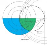
I think I am getting old and forgot what I said years before. My #47 post is not correct. I dug out an old graphics I did before. So, even the arm has underhang, the arm can still skate inward. Only if the arm locates at the Thales circle, the arm is stationary, tangential to the groove, and no skating.
This is also why I don't agree to say overhang causes skating since the arm can still skate inward when the arm has underhang.
The video does show the arm has outward skating at 0.16 seconds.
Attachments
Apologies, when you mentioned in or out skating I thought you meant constant and not skate to equilibrium.The video does show the arm has outward skating at 0.16 seconds.
"Bring forward what is true, write it so that it is clear, defend it to your last breath"
“Nothing is more practical than a good theory”
Ludwig Boltzmann.
I took a risky decision to install a cartridge on the working model tonearm. This meant devising a “counterweight” to allow the tonearm to achieve a useable VTF.
I had a vintage Empire 2000E unlikely to be used again, so it has taken one for the team. It has an unusually wide suggested VTF range, which is an advantage, and with the premise that the tonearm performs as intended, will only experience trivial side-force. The tonearm is one ugly mother, but hey, it’s not a beauty contest.
The stylus tracks on a clear acrylic disc, which sits on an actual LP. This gives some awareness of where it is sitting in normal operation.
The tonearm is the 25 cm version, with a different set of pivots, strut length, pivot location, bearing location, compared to the 15 cm original tonearm.
The video below shows that the performance is consistent with all of the previous demonstrations.
Tracking on a smooth disc is the standard for demonstrating the effect of side-force. According to the theory behind this tonearm, near tangential tracking occurs on the specific path enforced by the rear circle strut. It is practically impossible to consistently place the stylus precisely on the tangential path, because both the stylus and the groove are obscured when viewed from above, and from the side, parallax makes accuracy impossible. Anyway, making the best estimate, the initial stylus location placed just off the tangential path, the tonearm swings outwards or inwards until tangency is establish, where it remains. In the later part of the video, the stylus is deliberately misplaced to induce inwards or outwards skating until tangency is established.
The significant challenge to producing a useable tonearm, is to come up with a way of controlling/eliminating the VTF increase as the stylus tracks inwards. My machinist/engineer collaborator has a number of proposals to handle this.
Tonearm skating with cartridge - YouTube
I couldn't possibly comment.😀
“Nothing is more practical than a good theory”
Ludwig Boltzmann.
I took a risky decision to install a cartridge on the working model tonearm. This meant devising a “counterweight” to allow the tonearm to achieve a useable VTF.
I had a vintage Empire 2000E unlikely to be used again, so it has taken one for the team. It has an unusually wide suggested VTF range, which is an advantage, and with the premise that the tonearm performs as intended, will only experience trivial side-force. The tonearm is one ugly mother, but hey, it’s not a beauty contest.
The stylus tracks on a clear acrylic disc, which sits on an actual LP. This gives some awareness of where it is sitting in normal operation.
The tonearm is the 25 cm version, with a different set of pivots, strut length, pivot location, bearing location, compared to the 15 cm original tonearm.
The video below shows that the performance is consistent with all of the previous demonstrations.
Tracking on a smooth disc is the standard for demonstrating the effect of side-force. According to the theory behind this tonearm, near tangential tracking occurs on the specific path enforced by the rear circle strut. It is practically impossible to consistently place the stylus precisely on the tangential path, because both the stylus and the groove are obscured when viewed from above, and from the side, parallax makes accuracy impossible. Anyway, making the best estimate, the initial stylus location placed just off the tangential path, the tonearm swings outwards or inwards until tangency is establish, where it remains. In the later part of the video, the stylus is deliberately misplaced to induce inwards or outwards skating until tangency is established.
The significant challenge to producing a useable tonearm, is to come up with a way of controlling/eliminating the VTF increase as the stylus tracks inwards. My machinist/engineer collaborator has a number of proposals to handle this.
Tonearm skating with cartridge - YouTube
From my observation two things need to be established before no skating force occurred in a passive tonearm:
1) the stylus & cantilever obviously have to be in tangent with the radius.
2) the stylus & cantilever and pivot point have to form a straight line, hence the evidence of the "string test."
When these two things are established, no skating force exist, given a perfectly centric record or a blank groove disc.
Hi Bon, If you put the needle down in the groove where it is not in tangent does the pivot point move so that the tangent is restored? If so you have found the Holy Grail.
Does it stay in tangent if once placed in position? ie Does it have any stability?
I couldn't possibly comment.😀
In this demonstration, where is your horizontal pivot?
From this you can calculate your effective length and your tangency point.
From the video it seems the effective length origin is at the vertical pivot instead of the horizontal pivot as it would be in a production model.
Also, your effective length origin changes when you move the arm, creating a new tangency point and that is what your arm tends to, not true tangency for this topology.
When I was still fighting with this arm geometry, I had a vertical pivot attached to a fixed linkage above the linear bearing, this meant a shorter arm of fixed length.
Your linear bearing would then only have to deal with 2DOF instead of 3 which is much harder.
Good luck and keep going.
From this you can calculate your effective length and your tangency point.
From the video it seems the effective length origin is at the vertical pivot instead of the horizontal pivot as it would be in a production model.
Also, your effective length origin changes when you move the arm, creating a new tangency point and that is what your arm tends to, not true tangency for this topology.
The significant challenge to producing a useable tonearm, is to come up with a way of controlling/eliminating the VTF increase as the stylus tracks inwards
When I was still fighting with this arm geometry, I had a vertical pivot attached to a fixed linkage above the linear bearing, this meant a shorter arm of fixed length.
Your linear bearing would then only have to deal with 2DOF instead of 3 which is much harder.
Good luck and keep going.
In this demonstration, where is your horizontal pivot?
The vertical and horizontal bearing shafts meet in a "tee" configuration inside the HDPE slider carriage up inside the tonearm u-section.
From this you can calculate your effective length and your tangency point.
Yes, this is exactly it.
From the video it seems the effective length origin is at the vertical pivot instead of the horizontal pivot ....
They are at the same location. Maybe the video angle is misleading you.
Also, your effective length origin changes when you move the arm, creating a new tangency point and that is what your arm tends to, not true tangency for this topology.
Yes, the length changes and the arm simultaneously rotates to a new point on the (near) tangency path. It may be the play in the pivots that you are seeing. In fact it is this play that allows the misalignment that leads to the tangency seeking behaviour I deliberately try to expose. This is a rough working model to explore the concept. In a, proper prototype, precision bearings and the the geometry don't allow any departure from tangency. When it moves it can only follow a tangential path.
When I was still fighting with this arm geometry, I had a vertical pivot attached to a fixed linkage above the linear bearing, this meant a shorter arm of fixed length.
Your linear bearing would then only have to deal with 2DOF instead of 3 which is much harder.
That is our solution too, like a version of the Dynavector 507 tonearm but the two tonearm components in straight line.
Thanks for taking the time to comment.
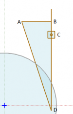
Perhaps lets clear up some terms.
A = Horizontal Pivot
B = Pivot, another horizontal?
C = Linear Bearing (Currently 3DOF, linear, rotation & vertical pivot)
D = Stylus tip
AD is your effective length and this will determine your tangency.
Because AB cannot rotate around A (currently), BD is what is determining the tangency in the video because of the extra effective horizontal pivot at B. I'm going to assume this is not the intended purpose if C is strict 3DOF and AB is allowed to rotate.
AD is longer than A-->spindle, so there is no zero skate condition anywhere for the arm in this form.
Please clarify if my assumptions are incorrect.
Attachments
Bon,
I have no doubt that the geometry of your arm is correct and works. Your geometry is actually a variant of Birch geometry. But if you want the arm to work in reality, you need a mechanism to ensure that all the locations of the stylus are on the Thales circle as I call it before. Once you add such a mechanism, things may get complicated.
Jim
Last edited:
Perhaps lets clear up some terms.
A = Horizontal Pivot
B = Pivot, another horizontal?
C = Linear Bearing (Currently 3DOF, linear, rotation & vertical pivot)
D = Stylus tip
AD is your effective length and this will determine your tangency.
Because AB cannot rotate around A (currently), BD is what is determining the tangency in the video because of the extra effective horizontal pivot at B. I'm going to assume this is not the intended purpose if C is strict 3DOF and AB is allowed to rotate.
AD is longer than A-->spindle, so there is no zero skate condition anywhere for the arm in this form.
Please clarify if my assumptions are incorrect.
Hi 2wice.
Hi. I am sorry my description is unclear.
I will use the diagrams in my post #21.
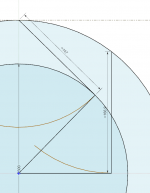
Diagram 1, in the 4th quadrant is the fixed location of a horizontal bearing.
A strut with a determined length is connected here with a frictionless bearing.
The other end of the strut is connected to the rear end of the tonearm by another frictionless horizontal bearing fixed to the tonearm rear.
With the stylus in the outer groove, the strut (green) joins the tonearm (blue) on the horizontal axis at a point left of the origin.
Fixed at the origin is the sliding, vertical and horizontal bearing. The tonearm will pass through this point under all positions.
Starting at the outer groove, the stylus at (25,0) will follow the tangential path as it is pulled by stylus-groove friction with disc rotation.
The tonearm sliding through the bearing at the origin, has a rear path lying in the 3rd quadrant.
The three (green, purple, black) radial lines in the 4th quadrant indicate the position of the rear strut with the stylus in the outer groove, central groove, inner groove.
In each position of the stylus on the tangential (red) path the tonearm passes through the vertical/horizontal bearing location at the origin. The distance from the origin to the stylus is the effective length and is constantly changing (increasing for perfectly circular, centred discs, but sometimes decreasing for non-centred discs).
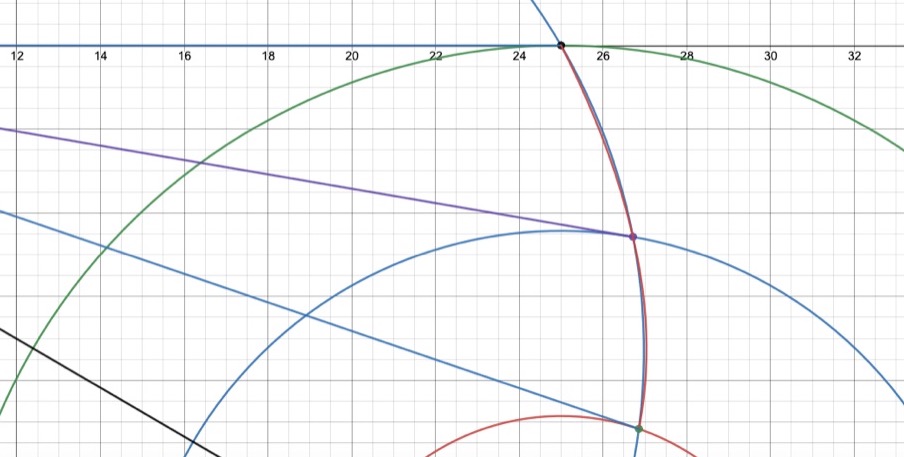
Diagram 2, blows up the rear stub region and for the 3 reference radii (outer, centre, inner grooves) shows the tonearm rear horizontal pivot location and connection to the tonearm, which passes through the horizontal/vertical bearing at the origin.
Diagram 3, shows the blown up stylus end under the same configuration. The stylus is always tangential to the groove with tonearm pivot location fixed at the origin.
The tonearm effective length is increasing and tracking is always tangential.
It may help to consider rotating the rear end strut clockwise about the 4th quadrant pivot and observing how the tonearm slides through the origin.
The actual perfect tangential rear end and corresponding stylus (Thales) paths are blue and red. The circular strut approximation are respectively black and blue.
The two sets of paths are virtually indistinguishable when overlaid.
Hope this answers your questions.
Bon
Last edited:
The distance from the origin to the stylus is the effective length
I hope it works out, good luck.
Last edited:
diagrams
I will use the diagrams in my post #21.
Diagram 1, in the 4th quadrant is the fixed location of a horizontal bearing.
A strut with a determined length is connected here with a frictionless bearing.
The other end of the strut is connected to the rear end of the tonearm by another frictionless horizontal bearing fixed to the tonearm rear.
With the stylus in the outer groove, the strut (green) joins the tonearm (blue) on the horizontal axis at a point left of the origin.
Fixed at the origin is the sliding, vertical and horizontal bearing. The tonearm will pass through this point under all positions.
Starting at the outer groove, the stylus at (25,0) will follow the tangential path as it is pulled by stylus-groove friction with disc rotation.
The tonearm sliding through the bearing at the origin, has a rear path lying in the 3rd quadrant.
The three (green, purple, black) radial lines in the 4th quadrant indicate the position of the rear strut with the stylus in the outer groove, central groove, inner groove.
In each position of the stylus on the tangential (red) path the tonearm passes through the vertical/horizontal bearing location at the origin. The distance from the origin to the stylus is the effective length and is constantly changing (increasing for perfectly circular, centred discs, but sometimes decreasing for non-centred discs).
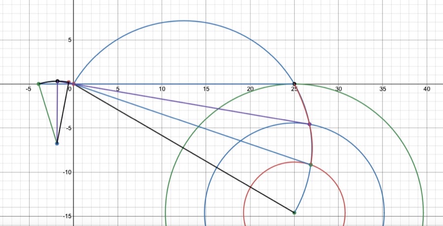
Diagram 2, blows up the rear stub region and for the 3 reference radii (outer, centre, inner grooves) shows the tonearm rear horizontal pivot location and connection to the tonearm, which passes through the horizontal/vertical bearing at the origin.
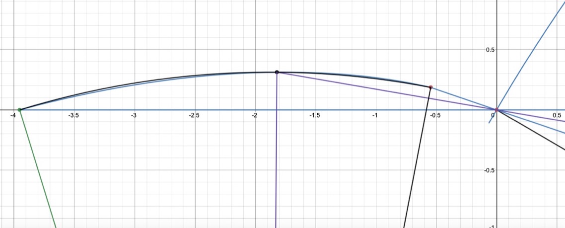
Diagram 3, shows the blown up stylus end under the same configuration. The stylus is always tangential to the groove with tonearm pivot location fixed at the origin.
The tonearm effective length is increasing and tracking is always tangential.
It may help to consider rotating the rear end strut clockwise about the 4th quadrant pivot and observing how the tonearm slides through the origin.
The actual perfect tangential rear end and corresponding stylus (Thales) paths are blue and red. The circular strut approximation are respectively black and blue.
The two sets of paths are virtually indistinguishable when overlaid.
Very clever idea. The only difficulty is the sliding bearing at the origin. It must be tight tolerance and zero friction at the same time, how will it be achieved?
Very clever idea. The only difficulty is the sliding bearing at the origin. It must be tight tolerance and zero friction at the same time, how will it be achieved?
I am open to any suggestions. There is similar technology required in many of the parallel tracking tonearms, though I am not a fan of Rockport style air bearing, for practical reasons (cost, complexity etc). I am aiming for a purely passive solution. Many printers, CNC machines etc, have similar requirements, so there should be options that are not too expensive. It probably involves a low friction engineering plastic machinable to high accuracy.
- Home
- Source & Line
- Analogue Source
- A tangential tracking pivoting tonearm