Let me give it a try.
When both enclosures are connected to PE, a coupling capacitor at the far end may be used to suppress RF because the shield could act as an antenna. Although quite possible, I have never experienced any problem without this cap with a GSM or radio transmitter near the cable, so I never apply this somewhat complex cap.
Now for equipment fed from Battery or a wall wart, the interconnect shielding could very well be connected at both ends to the the enclosures, but in case of the very sensible Head Amp, I have chosen not to do, but to give it its own direct PE connection because the wall wart is producing quite some pollution that I didn’t want it to be injected in the next stage.
Without this PE connection to the Head Amp, the wall wart causes an enormous amount of very strong mains harmonics in the spectrum, so these guys are producing quite some dirt. But as shown in the above spectra, with the PE connected to the Head Amp’s analog gnd, in this very case the noise spectrum is as clean as with a battery (Power Bank)
Hans
I have to admit removing mains harmonics was always a challenging task for me. Admittedly, my lab is 6ft. away from the house 200 amp electrical panel, but I still don't understand how some people (you included) get these absolutely clean spectra? Not even a few nV which would be clearly visible in the spectra after x1000 gain?
I understand balanced connections, but your measurement preamp is single ended, how was it shielded/configured so that again not even a few nV of mains harmonics are leaking in? 10nV of 50Hz at the shorted input (-160dB) falls in a single bin and would be clearly visible against an -190dB noise floor. Mine is shielded in 12mm of aluminum and 5nV input equivalent 50Hz is about the best I can get (see #1609, 50Hz is -165dB equivalent at the input)
And I have not even looked at the PSRR yet. AD797 has an excellent 130dB at low frequencies. Subtract the input stage gain of 34dB, that leaves 96dB. Meaning that 1V power supply noise creates about 15uV of noise at the AD797 output, or about 300nV of equivalent noise at the preamp input (ignoring the other 2 gain stages PSRR). One would need less than 1mV of power supply noise (mains ripple, etc...) to be able to not see on the spectra the input equivalent noise contribution. Look with a sensitive scope at a regular power supply output and estimate the RMS noise voltage... 1mV is doable, I did it with TI RF +/- regulators, but it is far from trivial (regulator compensation, filtering, etc...).
And I am not done yet, 60dB gain @1KHz is not much for a low output MC, it is 0.2-0.5V at the RIAA preamp output, but it also means an overall 80dB gain at 20Hz. After the signal hits the 7950us pole there is still an excess gain of about 11dB gain @50Hz and 5dB @100Hz. At least the cartridge and the cartridge wiring to the TT jacks are not collecting anything?
And I'm still not done yet, but I don't want to get into balanced cables CMRR, based on the cables geometry. All I can say is that shielded twisted pairs seem to be the best, and that since contrary to what people believe it is the magnetic field that creates most problems, and not the electric field, which is attenuated by a good shielding; for regular audio shielding, the magnetic field is not attenuated at all and happily induces mains harmonics even in what appears to be a perfectly shielded cable. And unfortunately shielded twisted balanced cables are not common for audio, AFAIK. Otherwise, you'll be shocked what is the result of connecting a 1m of shielded (and shorted at the end) single ended cable at my high impedance preamp input, how do you connect your head amp to the measurement preamp for noise measurement purposes?
Figure out what this means in terms of eliminating mains harmonics contamination, my answer, until somebody enlightens me, is "I don't know how to do it".
Last edited:
Maybe Linear Technology appnote 159 will provide some of the desired illumination. It definitely illustrates the kind of hiccups to be encountered.
I like to think that for both electrostatic and magnetic coupling, there is a certain type of prototypical circuit that facilitates it. For the former, it is large, exposed high impedance nodes, for the latter it is large, low impedance loops. I would not be surprised if there were some sort of bizarre topological transformation from one world to the other that would show them as equivalent, but I am not a mathematician. Something like the dual transformation for filters.
I like to think that for both electrostatic and magnetic coupling, there is a certain type of prototypical circuit that facilitates it. For the former, it is large, exposed high impedance nodes, for the latter it is large, low impedance loops. I would not be surprised if there were some sort of bizarre topological transformation from one world to the other that would show them as equivalent, but I am not a mathematician. Something like the dual transformation for filters.
Last edited:
Maybe Linear Technology appnote 159 will provide some of the desired illumination. It definitely illustrates the kind of hiccups to be encountered.
I know the app note; my problem is not measuring 0.3nV/rtHz (in fact I got down to 0.15nV/rtHz (when I measured my 64 parallel BF961 gain stage, results are buried somewhere on this forum), that’s easy with autocorrelation (although it takes an awful amount of time), but the mains harmonic contamination. I get an itch each time I see those crystal clear spectra after an 80dB gain, with what appears to be less than 1nV input equivalent mains harmonic components.
Per the app note, triple shielding including one layer of mu metal would certainly help; never tried that, but I will one day.
P.S. 1mV power supply harmonic noise is certainly not a problem with batteries, perhaps possible by cascading regulators (although wiring is non trivial), but with a simple wall wart (transformer, bridge, electrolytic)??? Or a switching wall wart??? Colour me blue, I am having a very hard time interpreting such a result. I am certainly missing something and I was never able to understand what.
Last edited:
I wonder at what point the ground loop of the two channels' shields (if truly common on both ends) contributes.
Then, the stray capacitive coupling from mostly unshielded cartridge wiring, internal and external, to shield. Pin 1 problem, etc. Probably minor with proper floating source and proper shield termination, but you guys are talking about crazy small numbers.
For a really good Shield, I'd recommend the Smith & Wesson M&P in 9mm. About 19 ounces, so you can carry two for stereo. Arf!
All good fortune,
Chris
JN (in a different, meandering, unending thread that must not be named) made an interesting point that the usual higher level single-ended "interconnect" cables, with shields carrying signal return and common at both ends, *share* the signal returns. Each shield carries half of that channel's signal return current, half of the the other channel's. Obvious(after it was pointed out to me)ly not the model for coaxial noise immunity.
God and the Devil dwell together in the details.
Always the best fortune,
Chris
God and the Devil dwell together in the details.
Always the best fortune,
Chris
My first reaction is to always go for the brute-force solution: telescoping grounds around other telescoping grounds. Class A, vacuum valves, all that old stuff.
But for wiring, it's easy enough to separate signal (two wires, kiddies!, or four if it's really noisy there) from every shield. Then it's just a judgment call on where to connect all the bloody shields. Then, keep 'em away from signal "ground". (B. Putzeys' G-word article reference).
A real brute-force solution would involve active devices in the headshell. Like everything else analog, was done more than a half century ago.
Kiss, kiss, bang, bang. (Pauline Kael reference)
Last edited:
And has the same problems it had 50 years ago. re-wire tonearm or hoofing great capacitors. Clearaudio will sell you one clearaudio electronic GmbH - absolute phono, The world's first active headshell moving coil phonostage for £10,500
In my personal experience loops and incorrect connections of the mains gnd are the most frequent cause of mains pollution.I have to admit removing mains harmonics was always a challenging task for me. Admittedly, my lab is 6ft. away from the house 200 amp electrical panel, but I still don't understand how some people (you included) get these absolutely clean spectra? Not even a few nV which would be clearly visible in the spectra after x1000 gain?
I understand balanced connections, but your measurement preamp is single ended, how was it shielded/configured so that again not even a few nV of mains harmonics are leaking in? 10nV of 50Hz at the shorted input (-160dB) falls in a single bin and would be clearly visible against an -190dB noise floor. Mine is shielded in 12mm of aluminum and 5nV input equivalent 50Hz is about the best I can get (see #1609, 50Hz is -165dB equivalent at the input)
1) When first testing everything, isolated from my audio set, just Head Amp (HA) and 60dB measurement amp (MA), set up was as follows:
The 60dB SE MA was battery powered and driven from the HA's SE output.
The MA's output went to Scope+PC, the latter being connected to mains gnd.
(The MA powered from a wall wart gave lots of mains harmonics in the noise spectrum, most likely because the MA is not differential. That made the choice for batteries an easy one.)
So in effect, starting from the PC and through the Scope all signal grounds became connected to mains gnd with no possible gnd loop.
However when trying to additionally connecting the HA's signal gnd to mains gnd, the mains harmonics popped almost out of the screen, confirming the damage a gnd loop can do.
With the used setup, spectra from the 34dB Gain HA where clean with a 1R input resistor simulating the cart, for the Diff Current as well as for the Diff Voltage modules.
The spectra were clean with the Power Bank Battery and also with 2 different 5Watt USB mains adapters, and the Head Amp was not even encapsulated in an enclosure !
However with a 10Watt mains adapter several mains harmonics became visible.
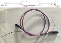
2) The next step whith HA tested as part of the Audio set, this time being differential/balanced from start to end and with the cart connected, I was already quite happy with the results, bus as shown a few postings before, I had forgotten to connect a cable shield that even completely removed the remaining 50Hz component after connection.
For convenience to keep things universal, I have used RCA interconnects between Cart/ HA and HA/MC phono amp, but in both cases with a shield that is detached from the connector, with separate wires to be connected to an enclosure.
See the first and second image below.
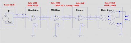
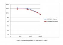
Some CMRR measurement results all three made from 20Hz to 20Khz.
- The HA's measured CMRR with closely selected components is above 50dB
- The third image below shows the CMRR of my diff MC phono amp in combination with the preamp behind.
- The Main Amps have a measured >90dB CMRR in the Audio band.
If you want some more details, I'll be happy to provide them.
Hans
.
P.S. Just as additional info: When not connecting the HA's signal gnd to PE makes no difference at all when using the Power Bank, but with the USB mains adapter mains harmonics are all over the place.
So the PE completely neutralises these mains harmonics.
Attachments
Last edited:
That's a valid remark.I should note that at some point the cartridge itself will be picking up more mains hum than everything else, so we pretty much have a hard limit unless the whole front end is in a seperate metal box with no mains!
I have only measured the noise spectrum in the complete Audio set with the Current modules that present a short circuit to the Cart.
Could be that the Voltage modules with Rin is 260R make picking up mains a bit more susceptible.
I will test this and report back the results.
Hans
In my personal experience loops and incorrect connections of the mains gnd are the most frequent cause of mains pollution.
1) When first testing everything, isolated from my audio set, just Head Amp (HA) and 60dB measurement amp (MA), set up was as follows:
The 60dB SE MA was battery powered and driven from the HA's SE output.
The MA's output went to Scope+PC, the latter being connected to mains gnd.
(The MA powered from a wall wart gave lots of mains harmonics in the noise spectrum, most likely because the MA is not differential. That made the choice for batteries an easy one.)
So correct me if I'm wrong, for measurement purposes both the HA and the MA were battery powered, correct? That would explain it, but then how come your comment in #1632 and #1633 (with the clean spectra, that is still a measurement) that USB bank or wall wart makes no difference? That's what I find strange, even more so you are using a PC, not really famous for low noise environment. And no shielding for the HA, almost unbelievable! After a total gain of 34dB+60dB, not even a microvolt of mains harmonic at the output, meaning less than 20pV equivalent at the input. There is definitely more than "no ground loops" here.
And you are not alone, I've seen the same with other results, it is frustrating. I'm fighting any quarter of nanovolt contamination and others have absolutely no problem in getting absolutely clean results. OTOH, I also see in professional papers measurements affected by the mains harmonics, to the point I started to take this harmonic contamination as a proof of results credibility.
Speaking about PCs, I recently acquired a brand new 3rd Generation Focusrite 2i2 interface, USB powered. Excellent performance, but even with the balanced input shorted at the input jacks I can still see crud (mains harmonics and other) creeping in the output spectra. Once again, not a big deal, but the same question about perfectly clean spectra you posted arises.
How did you cleanly measure 120dB of PSRR? I'm aware of the usual PSRR measurement techniques, but in practice that's another thing that I was never able to do.
And I think I know why that is.P.S. Just as additional info: When not connecting the HA's signal gnd to PE makes no difference at all when using the Power Bank, but with the USB mains adapter mains harmonics are all over the place.
So the PE completely neutralises these mains harmonics.
Wall wart style 2-prong SMPS like your USB power adapter have a tendency to connect the mains filter caps (typically 2x2n2 or somesuch) to secondary-side ground. So your head amp ground is being pulled towards 1/2 * 230 V~, and now the poor MC amp's input CMRR has to do all the heavy lifting since the cable shield is not hooked up. Not to mention potential capacitive coupling to the head amp's input end.
I bet you could connect the cable shield at the MC amp end and the mains harmonics would disappear entirely, or close to it anyway. A dedicated PE connection still is lower-impedance and with the shield not having to carry any current I would assume your usual setup to be higher performance, but whether you would actually see the difference, I don't know. If this measurement setup doesn't show it I don't know what would!
BTW, regarding the electrolytic capacitor adventures posted here earlier - did you know that it has actually been shown that capacitors can be characterized for leakage by 1/f noise, i.e. the latter being a side-effect of the former? Very low ESR is generally connected to high leakage, so the findings make complete sense. One to be aware of when you're relying on RC filtering for PSRR or have high-impedance nodes tied to caps.
Leakage is also tied to longevity (where ripple is not an issue). The orange low leage ELNAs in the MPX section of tuners are generally still good after 4 decades despite never seeing much of any DC, regular 10µ/16V polars kept under similar conditions are generally toast.
Last edited:
. But as shown in the above spectra, with the PE connected to the Head Amp’s analog gnd, in this very case the noise spectrum is as clean as with a battery (Power Bank)
Hans
I just noted this. I had assumed only case connected to PE as the power supply is effectively floating but for the wall wart case that makes sense.
MA was always powered by a battery but the HA was not just powered by a Power Bank in the test setup but also by several mains adapters.So correct me if I'm wrong, for measurement purposes both the HA and the MA were battery powered, correct?
I mentioned for the Test Setup with the MA + HA that “The spectra were clean with the Power Bank Battery and also with 2 different 5Watt USB mains adapters, and the Head Amp was not even encapsulated in an enclosure !
However with a 10Watt mains adapter several mains harmonics became visible. “.
The images in #1632 and #1633 that you refer to, were measured spectra with the HA as part of a complete Audio set with Cart connected. So in this case no MA in use but a fully differential in/out MC Riaa phono preamp instead.but then how come your comment in #1632 and #1633 (with the clean spectra, that is still a measurement) that USB bank or wall wart makes no difference? That's what I find strange, even more so you are using a PC, not really famous for low noise environment. And no shielding for the HA, almost unbelievable! After a total gain of 34dB+60dB, not even a microvolt of mains harmonic at the output, meaning less than 20pV equivalent at the input. There is definitely more than "no ground loops" here.
And you are not alone, I've seen the same with other results, it is frustrating. I'm fighting any quarter of nanovolt contamination and others have absolutely no problem in getting absolutely clean results. OTOH, I also see in professional papers measurements affected by the mains harmonics, to the point I started to take this harmonic contamination as a proof of results credibility.
I fail to understand your 20pV calculation. Level of the shown spectra are at 312pV/rtHz, so mains harmonics are less than 312pV and not 20pV.
Because the 2i2 is powered from the PC’s noisy supply through the USB interface, it will be susceptible to inflow of mains harmonics. The 2i2 is like a Diff HA and a SE MA in one box, were my MA had to be powered by batteries.Speaking about PCs, I recently acquired a brand new 3rd Generation Focusrite 2i2 interface, USB powered. Excellent performance, but even with the balanced input shorted at the input jacks I can still see crud (mains harmonics and other) creeping in the output spectra. Once again, not a big deal, but the same question about perfectly clean spectra you posted arises.
My Single Ended MA absolutely needed a battery supply to achieve a clean spectrum, as opposed to the diff MC Phono amp with its own separate PE connection that didn’t have to be supplied from batteries to get a clean spectrum.
So could it be that fully differential in/out, in combination with its own separate local connection to PE is the all-important reason why? For the time being, to my experience the answer is a clear yes.
A little bit diff as in the 2i2 does not work IMO. It should be either diff from start to end with a separate PE connection or alternatively SE, powered by batteries for the sensitive parts.
In case of my differential HA, the USB mains adapter has no direct connection to the signal gnd, and that, in combo with the diff topology, might be the reason why I can use a wall wart as long as the signal gnd is connected to PE, either from the PC in the measurement setup, or with its own PE connection in the fully differential Audio chain.
I did not mention PSRR but CMRR.How did you cleanly measure 120dB of PSRR? I'm aware of the usual PSRR measurement techniques, but in practice that's another thing that I was never able to do.
Testing the CMRR was done the “simple way” by connecting a signal generator’s signal between the short-circuited inputs and signal gnd.
Measured results do conform perfectly well to fig 12 in the AD797’s specs.
Scott did an excellent job with the design of this op-amp.
Hans
MA was always powered by a battery but the HA was not just powered by a Power Bank in the test setup but also by several mains adapters.
I mentioned for the Test Setup with the MA + HA that “The spectra were clean with the Power Bank Battery and also with 2 different 5Watt USB mains adapters, and the Head Amp was not even encapsulated in an enclosure !
However with a 10Watt mains adapter several mains harmonics became visible. “.
That's exactly what I don't understand:
- Single ended measurement setup: HA+MA+PC
- HA powered from 5W USB mains adapter (alleged switching)
- MA powered by batteries
- HA not shielded
- Total gain, about 96dB (36dB HA + 60dB MA)
- Cables used, connectors, unknown (type, length)
Result: less than 312pV (input equivalent) of mains harmonics at the output (20pV was considered as excess over the 312pV/rtHz "floor" to make it visible on the spectra).
I'll post later the effect of a 30cm single ended cable (shorted) at my MA input. This effect has nothing to do with ground loops, etc...
Correct for the above, with the following additions:That's exactly what I don't understand:
- Single ended measurement setup: HA+MA+PC
- HA powered from 5W USB mains adapter (alleged switching)
- MA powered by batteries
- HA not shielded
- Total gain, about 96dB (36dB HA + 60dB MA)
- Cables used, connectors, unknown (type, length)
Result: less than 312pV (input equivalent) of mains harmonics at the output (20pV was considered as excess over the 312pV/rtHz "floor" to make it visible on the spectra).
I'll post later the effect of a 30cm single ended cable (shorted) at my MA input. This effect has nothing to do with ground loops, etc...
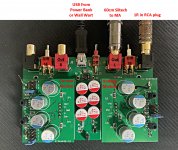
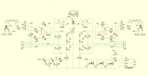
-Unshielded HA on mouse pad, powered from 5W USB adapter having no direct connection with signal gnd (called Null here), see second image below.
-HA diff input terminated with 1R resistor, no cable connected at this side
-connection between HA and MA with 60cm Siltech FTM4 Gold cable with WBT RCA connectors, driven from HA's Diff to SE converter.
-Connection between MA and scope a 60cm 50R coax cable.
Picture is still with the Nichicons that were later replaced by Panasonics FM.
Hans
.
Attachments
- Home
- Source & Line
- Analogue Source
- Richard Lee's Ultra low Noise MC Head Amp