Hi guys, I've completely updated the MC Head Amp Compendium - second link in the first post of this thread.
Enjoy!
Enjoy!
Thank you for this tremendous work! Excellent summary of almost all known topologies.
The very simple 'Maxwell' circuit gets a little bit overrated in your ranking - it seems you used the distortion ppm values as noise values!
The very simple 'Maxwell' circuit gets a little bit overrated in your ranking - it seems you used the distortion ppm values as noise values!
Could you also please check the noise values for the 'Hawking' circuit - its the only one with (impossible) low noise value for a 10 Ohm generator (lower than 5 Ohm)
Hi guys, I've completely updated the MC Head Amp Compendium - second link in the first post of this thread.
I guess I'm missing something... How can a circuit (Maxwell) with Rg=5/10ohm have noise of 110/304pV/rtHz?
Both noise values are lower than the Rg noise. If you subtracted the Rg noise from the simulation, than you should specify that.
Sn08, I've entered the distortion figures and not the noise figures - I'll update accordingly.
Aboos - values swapped - I'll update accordingly.
note that in all sims, Vinoise is the generator noise + the circuit noise - there is no subtraction taking place.
Thanks
Aboos - values swapped - I'll update accordingly.
note that in all sims, Vinoise is the generator noise + the circuit noise - there is no subtraction taking place.
Thanks
Last edited:
Sn08, I've entered the distortion figures and not the noise figures - I'll update accordingly.
Aboos - values swapped - I'll update accordingly.
note that in all sims, Vinoise is the generator noise + the circuit noise - there is no subtraction taking place.
Thanks
IMO, including Rg the generator noise is only clouding the circuit performance. The very low noise designs look as noisy as the worse performers.
DeBroglie - paralleling 5 ZTX is useless, the Rc=50ohm current noise dominates the overall noise, anyway. Try with one ZTX with the same Rc, there won't be much of a difference in noise performance.
Feynman, same comment about paralleling, it is pointless. Re=5ohm plus Rg=5ohm covers the overall noise.
Planck, very hard to keep the currents balanced, plus it will drift with temperatire like crazy (-4mV/C Vbe)
Dirac, paralleling 3 BF862 with a common 22ohm source resistor is useless. 22ohm is larger than the noise of the paralleled JFETs. I don't buy the 100Hz corner noise frequency, I've measured enough BF862's and the noise corner frequency is barely under 300Hz, if that.
Scott was right. You have to include Rg because that is what dominates the noise in most of these practical circuits - especially Bipolar input versions. Best to worst (bip and JFET) is 3x or c. 10 dB, and amongst the bipolar its c. 1 to 1.5 (3dB) The upshot of this is don't go creating monstrosities with 16 BF862 in parallel to get 0.28 nV/rt Hz because you are wasting money. And it looks ridiculous - like taking a baseball bat to a cocktail party to impress the women.
DeBroglie. The collector load resistor is not the dominant noise source. How can it be an issue on the DeBroglie and not on the Pauli?
Feynman - you get a 20% improvement. But, Rg remains the elephant in the room, so you can simply remove the parallel devices and still get good performance so I agree in part with your comment.
Planck output is AC coupled. You can shield the transistors from air currents and bond them together. Get creative.
Dirac - noise goes from 1.5nV/rt Hz to just under 1.1nV/rt Hz for the 'cost' of an additional 2 BF862's. You can lower Rsource but it requires more complex biasing. I am working on another version of this with Rsource c. 1 Ohm. It will have to wait until next week.
BF862 1/f - its just what's coming from the model so I cannot argue on that issue.
Scott was right. You have to include Rg because that is what dominates the noise in most of these practical circuits - especially Bipolar input versions.
An I thought you are comparatively analyzing circuits noise performance. What's the purpose of including Rg which only levels the performance of various topologies and configurations?
DeBroglie. The collector load resistor is not the dominant noise source.
You probably missed the discussion about spice errors due to high load current noise, scroll a couple of pages back. Try to simulate with 2 ZTX instead of 5 and see how large of a noise difference you get. Since all transistors are running at a total constant current of some 3mA (by inspection), the 1/2gm number is the same whatever number of ZTX you are paralleling. The only benefit of paralleling ZTX devices is to lower the RB, which is much lower than (you guessed) Rg, so it doesn't matter, anyway.
Planck output is AC coupled. You can shield the transistors from air currents and bond them together. Get creative.
Yes, it works, until the output approaches one of the tiny rails (+/-0.75V floating), can you spell quasi saturation? I'll save the dynamic range discussion for later.
Last edited:
The point here is if the noise is root 2 x Rg you are at the best cost (or effort if you prefer) performance point.
I can sim over temp on the Planck and see what it gives. I doubt it’s a disaster though.
Your point about high current noise still does not answer why the DeBroglie should fair worse than the Pauli or vice versa. I understand input noise current with lots of parallel bip devices but we are talking about the collector load resistor here Rc or are you meaning something else?
Bonsai,
Thanks for collecting all sorts of topologies in one document.
Just curious.
Where did you find a connection between Erwin Schroedinger and John Curl's patent, the first image in your documentation ?
I searched Wiki, with no result.
Hans
Thanks for collecting all sorts of topologies in one document.
Just curious.
Where did you find a connection between Erwin Schroedinger and John Curl's patent, the first image in your documentation ?
I searched Wiki, with no result.
Hans
Ok, because it's summer and holiday season in NA, I had the time to put together, out of curiosity, some of the ideas in this topic.
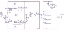
Schematic is attached. It's the adapted current mirrored version of the Leach head amp. Power supply is provided by a solar cell illuminated by four spectral matched white power LEDs, running at 350mA. The constant current is provided by a LM317.
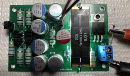
The solar cell has a measured open voltage of 2.7V and a short circuit current of 70mA. Way over what is needed for this pream, so the LED current could probably lowered to 150mA, if not even less. Current through transistors is about 5mA, so the whole setup takes only 10mA out of the solar cell current capability. The rest of the schematic is self explanatory. A photo of the finished and powered circuit is attached. All electrolytics are of the polymer type, for the lowest ESR, all resistors (with the exception of the 1k at the output, which is metal film) are of the wire wound type, for the lowest excess noise.
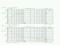
The gain is 24dB @ 1KHz, see attached. Unfortunately one of the issues with this pre is now obvious; the LF frequency response is lacking, for a MC cartridge we would need a drop @20Hz of less than 0.2dB (I'm not saying this is an absolute requirement, but some purists may protest for anything worse). This lack of LF response is obvious from a napkin calculation, 4x3900uF decoupling (a total of 8pcs.) or more would be required. The other option is to increase the supply voltage (use a different solar cell with higher open voltage) and then increase the collector resistors, proportionally.
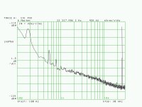
To measure the noise (input shorted) I used my low noise preamp, with a calibrated gain of 60dB, so the total gain is 64 dB. The output noise is attached, 450nV/rtHz, which renders an input referred noise of 280pV/rtHz. That's good, and reasonably close to the simulated value (200pV/rtHz). In fact, is close enough to be happy about the HF noise performance of the solar cell output, filtered by a 2200uF electrolytic.
The not so good part (actually, the really bad part) is the significant amount of LF noise, straight in the audio band. As you can see in the attached, @1KHz the noise is almost 6dB worse, which is 560pV/rtHz. Still good for a MC cartridge, but the whole complication with solar cell, LEDs, etc... is hard to justify at this noise level, you could get it with a much simpler setup. I have no idea why this increase in the LF noise (simulation tells (of course) jack ****) in particular because it does not appear to be 1/f noise, it could be still GR noise from the solar cell, insufficiently filtered out. I'll keep looking at this, I have enough boards and parts to do a few more experiments.
Schematic is attached. It's the adapted current mirrored version of the Leach head amp. Power supply is provided by a solar cell illuminated by four spectral matched white power LEDs, running at 350mA. The constant current is provided by a LM317.
The solar cell has a measured open voltage of 2.7V and a short circuit current of 70mA. Way over what is needed for this pream, so the LED current could probably lowered to 150mA, if not even less. Current through transistors is about 5mA, so the whole setup takes only 10mA out of the solar cell current capability. The rest of the schematic is self explanatory. A photo of the finished and powered circuit is attached. All electrolytics are of the polymer type, for the lowest ESR, all resistors (with the exception of the 1k at the output, which is metal film) are of the wire wound type, for the lowest excess noise.
The gain is 24dB @ 1KHz, see attached. Unfortunately one of the issues with this pre is now obvious; the LF frequency response is lacking, for a MC cartridge we would need a drop @20Hz of less than 0.2dB (I'm not saying this is an absolute requirement, but some purists may protest for anything worse). This lack of LF response is obvious from a napkin calculation, 4x3900uF decoupling (a total of 8pcs.) or more would be required. The other option is to increase the supply voltage (use a different solar cell with higher open voltage) and then increase the collector resistors, proportionally.
To measure the noise (input shorted) I used my low noise preamp, with a calibrated gain of 60dB, so the total gain is 64 dB. The output noise is attached, 450nV/rtHz, which renders an input referred noise of 280pV/rtHz. That's good, and reasonably close to the simulated value (200pV/rtHz). In fact, is close enough to be happy about the HF noise performance of the solar cell output, filtered by a 2200uF electrolytic.
The not so good part (actually, the really bad part) is the significant amount of LF noise, straight in the audio band. As you can see in the attached, @1KHz the noise is almost 6dB worse, which is 560pV/rtHz. Still good for a MC cartridge, but the whole complication with solar cell, LEDs, etc... is hard to justify at this noise level, you could get it with a much simpler setup. I have no idea why this increase in the LF noise (simulation tells (of course) jack ****) in particular because it does not appear to be 1/f noise, it could be still GR noise from the solar cell, insufficiently filtered out. I'll keep looking at this, I have enough boards and parts to do a few more experiments.
Attachments
Last edited:
The point here is if the noise is root 2 x Rg you are at the best cost (or effort if you prefer) performance point.
I can sim over temp on the Planck and see what it gives. I doubt it’s a disaster though.
Your point about high current noise still does not answer why the DeBroglie should fair worse than the Pauli or vice versa. I understand input noise current with lots of parallel bip devices but we are talking about the collector load resistor here Rc or are you meaning something else?
Temperature simulation without quasi saturation is BS.
Still don't understand why simulating with input short is not good enough for an apple to apple noise comparison.
You need a crash course in bipolar noise, there are essentially two sources, Rbb and the (approximative) 1/2gm equivalent collector current noise. If you divide this collector current noise by Beta, you get the input current noise (base current noise). At low currents, 1/2gm could dominate, for example @1mA 1/2gm=25ohm equivalent noise, that's why you need to push the collector current as high as possible to minimize this noise source (would be 2.5ohm @ 10mA) but then you pay by a larger input (base) current noise that drops voltage noise on Rbb and Rg. That's the beauty of the old unobtanium transistors, they had not only Rbb 1...2 ohm, but also Beta 600...1000 so the increase in the input current noise was not that bad.
At the collector node, you have @1mA a 25ohm current noise source (the transistor) and a 50ohm current noise source (the collector resistor). Since the transistor(s) are biased at constant Vbe, it doesn't matter you parallel 2 or 20 transistors, the 1mA will be shared and the equivalent current noise source will still be 25ohm, so no benefit in paralleling. 25ohm transistor vs. 50 ohm collector is not too bad, but you need to have Rc at least 3 times the equivalent 1/2gm to be able to more or less ignore the collector resistor current noise (since noise adds as power, so squared). For the rest, you do the math and get a good reading on noise.
The gain changes with generator resistance in these simple designs. If you short the input it’s circa Rload/(Re+re). Did you adjust for this?
For PSU, you may as well use a battery - charge when OFF. 350 mA is a hell of a current draw.
On some of the designs in the compendium, I actually backed collector current off in order to reduce current draw. I think 60mA for an MC pre pre is nuts.
The root 2 * Rg is simply a figure of merit thing. Reducing noise beyond that quickly results in diminishing returns which is why these simple Lee/Leach configurations are so good. You get great performance with little extra circuit effort.
“You need a crash course in bipolar noise” 😀
Last edited:
Bonsai,
Thanks for collecting all sorts of topologies in one document.
Just curious.
Where did you find a connection between Erwin Schroedinger and John Curl's patent, the first image in your documentation ?
I searched Wiki, with no result.
Hans
I’ve given all the circuits the names of famous physicists and at the bottom RHS of the slide you can click the link s d read about them in wiki
😉
The gain changes with generator resistance in these simple designs. If you short the input it’s circa Rload/(Re+re). Did you adjust for this?
For PSU, you may as well use a battery - charge when OFF. 350 mA is a hell of a current draw.
On some of the designs in the compendium, I actually backed collector current off in order to reduce current draw. I think 60mA for an MC pre pre is nuts.
The root 2 * Rg is simply a figure of merit thing. Reducing noise beyond that quickly results in diminishing returns which is why these simple Lee/Leach configurations are so good. You get great performance with little extra circuit effort.
“You need a crash course in bipolar noise” 😀
For the n-th time I wonder why am I wasting my time talking to you. You are not listening to any sensible sugestions or reasoning, being as obtuse as in the current feedback discussion. I was trying to help, but you go ahead by yourself, I'm out of here. Sorry for any inconvenience.
- Home
- Source & Line
- Analogue Source
- Richard Lee's Ultra low Noise MC Head Amp