So, with this schematic you get the theoretical values for noise, with the default NPN model, correct?
Then this boils down again to some differences in how simulators are handling the noise calculation.
The difference could be on how the simulator calculates gm with constant IE vs. constant VB.
This is what I get @ constant IE, 1...10mA step 1mA
For comparison, I'm attaching the results @ constant VB, 1...6mA step 1mA
Schematics for const. VB and const. IE are also attached.
Mystery solved... it's actually a rather stupid error I made. For the VB=const. mode, the VBE variation is, even for the NPN default model in Pspice, large enough to create a delta in gm that affects the simulated noise. At VB=6.6V, Ic is actually less that 6mA, leading to a higher simulated noise. When comparing noise equivalent resistors (simulated vs. calculated), the input referred noise is squared, which only makes the errors worse.
If I take into acount the VBE variation with VB and use for calculating the noise equivalent resistance the real collector currents, I get the same approximation as for constant IE, which is very good.
The non monotonic noise behavior was another stupid mistake I made, over 7mA the transistor saturates.
Case closed, at least for PSpice, the only question remaining is why is Hans getting correct results in LTSpice, for VB const. They should be affected by the same VBE variation error as in PSpice.
O.K, I have adjusted to Ic=30uA.No Hans I had earlier said Ic, sorry, Ic = 30uA, Rn = 1/2gm. I am looking at an individual device to check the model only and I see no deviations.
This is what I get with the ZTX851, RB set to 1R5.
Measured noise: 5.62nV/rtHz
1/2gm noise: 2.64nV/rtHz
Calculated Rbb: 1478 Ohm
A huge deviation so to see.
Hans
Attachments

O.K, I have adjusted to Ic=30uA.
This is what I get with the ZTX851, RB set to 1R5.
Measured noise: 5.62nV/rtHz
1/2gm noise: 2.64nV/rtHz
Calculated Rbb: 1478 Ohm
A huge deviation so to see.
Check the actual collector current.
Check the actual collector current.
30uA as specified in my posting to Scott.
Hans
30uA as specified in my posting to Scott.
Hans
Make the collector resistor 50k. At those current values, the resistor current noise matters.
With Rc=50k I get 2.78nV/rtHz which is 480ohm. Real Ic is 28.6uA, 1/2gm is 437ohm, not that bad.
That's a lot better.Make the collector resistor 50k. At those current values, the resistor current noise matters.
With Rc=50k I get 2.78nV/rtHz which is 480ohm. Real Ic is 28.6uA, 1/2gm is 437ohm, not that bad.
I get 2.72nV/rtHz at Ic=30.15uA, that's 444 Ohm versus 1/2gm=397 Ohm.
Quite comparable to your results.
Hans
That's a lot better.
I get 2.72nV/rtHz at Ic=30.15uA, that's 444 Ohm versus 1/2gm=397 Ohm.
Quite comparable to your results.
Mine were still with the default NPN model.
But yes, VBE variation and the collector resistor current noise covers pretty much all the delta between theory (1/2gm equivalent noise) and the simulated noise values.
I'll check which of the model parameters are affecting the noise, in principle none should, assuming KF=0 (no flicker noise), and other than through the VBE variation above (assuming the RC current noise always negligible).
And some still believe simulations are easy 😀.
That's a lot better.
I get 2.72nV/rtHz at Ic=30.15uA, that's 444 Ohm versus 1/2gm=397 Ohm.
Quite comparable to your results.
Good, that was what I was trying to say the current noise at the output has to be dominated by the collector current noise. BTW I don't find the impedance matching and RF type noise figure concepts to have anything to do with the Leach circuit. In general noise figure and impedance matching has little use in audio except in some transformer based applications.
That's where the DuraglitSpecial, DS excels. I made most of my noise measurements with a very large load resistors. With the usual RIAA MM stage, when you add the DS & MC cartridge, the MM stage often shows essentially the source noise of the usual <1k load resistor in DS. ie no change in noise when you turn DS on.Good, that was what I was trying to say the current noise at the output has to be dominated by the collector current noise.
A MM stage with <1k source will of course show much less noise than with the usual inductive MM cartridge.
It does in case of the common base DS. Common base has an optimum NF of 3dB at the matched Source which is also the Input Resistance.BTW I don't find the impedance matching and RF type noise figure concepts to have anything to do with the Leach circuit. In general noise figure and impedance matching has little use in audio except in some transformer based applications.
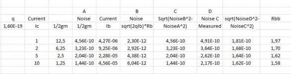
When I saw Hans' first table, I was tempted to do my 1980 Baxandall type analysis but it looks like syn08, Hans & Guru Wurcer have done most of the necessary work.When I increase the collector resistance with my previous measurements from 1mA to 10mA, the table becomes as below.
Rbb now varies between 1R58 and 1R97, quite a lot better as before.
But perhaps I should check if my single brain cell is still working. Hans, can you explain what are
- Current Ib: is that base current?
- sqrt(2qIb)*Rb
- is Rb actually rbb' ?
- Noise C measured: is that Noise Simmed by LTspice?
Last edited:
Ib is base currentHans, can you explain what are
- Current Ib: is that base current?
- sqrt(2qIb)*Rb
- is Rb actually rbb' ?
- Noise C measured: is that Noise Simmed by LTspice?
Sqrt(2qIb)*Rb is part of the input voltage noise caused by Ib and Rb
Rb used was the calculated Rbb, but outcome is neglectable in this case
Noise measured is what LTSpice has calculated
Hans
[*]is Rb actually rbb' ?
rbb' is typically just the resistance under the emitter as defined by, for instance, Grey and Meyer. I assume Rb includes all extrinsic contributions by metal, contact resistance, etc. I found it interesting (in 1974) how poorly base resistance (re: noise) was understood by folks who should have known better. Flavor of choice was big round emitters which are the worst possible geometry for low rbb'.
The input transistors on the 797 were designed to sacrifice some Re to reduce rbb' by a considerable factor. This required a layout rule violation that had to be signed off on by the fab guys. It was actually <0.5nV ready but there was no commercial viability for a part with the high Ib and Ib noise.
rbb' is typically just the resistance under the emitter as defined by, for instance, Grey and Meyer. I assume Rb includes all extrinsic contributions by metal, contact resistance, etc. I found it interesting (in 1974) how poorly base resistance (re: noise) was understood by folks who should have known better. Flavor of choice was big round emitters which are the worst possible geometry for low rbb'.
I though rbb' is the whole p/n base resistance, from the mean point in the active base region that acts as an effective base point, to the metal/semiconductor base contact. This is more than the resistance under the emitter.
As you say, the Spice RB is the sum of rbb' and the rest of the extrinsic components (base M/S contact, metallization, wire bonding).
I though rbb' is the whole p/n base resistance, from the mean point in the active base region that acts as an effective base point, to the metal/semiconductor base contact.
Possibly a fine point, I always though it was the region where the boundary conditions were easily defined so the integral that defined the resistance was simple and tractable. For uniform injection in the emitter it would be the edge of the emitter, after that there is an extrinsic (rbx) component simply computed from the base sheet and geometry.
Possibly a fine point, I always though it was the region where the boundary conditions were easily defined so the integral that defined the resistance was simple and tractable. For uniform injection in the emitter it would be the edge of the emitter, after that there is an extrinsic (rbx) component simply computed from the base sheet and geometry.
That's how I was taught, Rbb is the "base spreading resistance". Toshiba in the the application_note_en_20180914.pdf app note (google it, too large to attach here) on p. 8/28 seem to agree.
Attachments
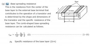
That's how I was taught, Rbb is the "base spreading resistance". Toshiba in the the application_note_en_20180914.pdf app note (google it, too large to attach here) on p. 8/28 seem to agree.
Yes the formula there covers the 0 to L region. Actually using centroid symmetry it would be -L/2 to L/2. Uniform injection gives a parabolic voltage distribution so that's were the factor of 1/3 comes from and integrating from 0 to L/2 and paralleling the two halves give 1/4 or the 1/12 net in the formula (IIRC). I was just talking about the little piece of p+ going from L to the actual contact, a trivial point.
There are of course some wild and wacky MMs out there with exceeding low inductance and resistance. For low noise willy waving I think Scott's Grado is the winner.A MM stage with <1k source will of course show much less noise than with the usual inductive MM cartridge.
.
Gratifying that you have cleared things up.
I would not spend any more time on Berkley Spice. It had its time but it is
unsupported now for 20 years. It seems that ngspice is the best alternative
to LT; it is based on bs3 but has 20 more years of bug removal and includes
newer things like Philips/NXP MEXTRAM, hspice etc and a suppert group that cares.
IIRC you wrote that you wanted to migrate to KICAD; that would be a natural
eco system for graphical circuit entry.
QUCS or QUCS-Studio seems also interesting, but it is not spice, only similar.
At least it can import spice models.
I'll check the original Berkley Spice source code for any clues on how noise is calculated.
I would not spend any more time on Berkley Spice. It had its time but it is
unsupported now for 20 years. It seems that ngspice is the best alternative
to LT; it is based on bs3 but has 20 more years of bug removal and includes
newer things like Philips/NXP MEXTRAM, hspice etc and a suppert group that cares.
IIRC you wrote that you wanted to migrate to KICAD; that would be a natural
eco system for graphical circuit entry.
QUCS or QUCS-Studio seems also interesting, but it is not spice, only similar.
At least it can import spice models.
Last edited:
That's how I was taught, Rbb is the "base spreading resistance". Toshiba in the the application_note_en_20180914.pdf app note (google it, too large to attach here) on p. 8/28 seem to agree.
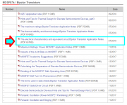
For those playing along at home, the download page is
Application Notes | Toshiba Electronic Devices & Storage Corporation | Americas – United States
and the title you wish to click upon is shown in the image file below
_
Attachments
- Home
- Source & Line
- Analogue Source
- Richard Lee's Ultra low Noise MC Head Amp