I was shocked to find AD797 used EVIL Ib cancellation 😱 I naively thought Guru Wurcer and AD had used some supa tech with dupa Rnv & supaBeta.The input transistors on the 797 were designed to sacrifice some Re to reduce rbb' by a considerable factor. This required a layout rule violation that had to be signed off on by the fab guys. It was actually <0.5nV ready but there was no commercial viability for a part with the high Ib and Ib noise.
What was the design hfe for the i/p transistors?
What was the current in the i/p stages?
If we knew that, can we guestimate hfe from the Current Noise spec?
For the n-th time I wonder why am I wasting my time talking to you. You are not listening to any sensible sugestions or reasoning, being as obtuse as in the current feedback discussion. I was trying to help, but you go ahead by yourself, I'm out of here. Sorry for any inconvenience.
Calm down. Take a breath.
All I asked was did you take into account the fact that the gain changes with generator resistance on these simple circuits.
(You are confusing me with someone else on the CFA thread. I don’t ever recall interacting with you on it - I started the thread and was a model of mannerlyness.)
Right, to keep Syn08 happy, I have added a graph in the compendium that subtracts the generator noise from the total input referred noise.
Quite a few of the simple circuits approach 100 pico V/rt Hz, but be warned they chew current (15mA and much higher). Also note in these circuits, I deliberately backed off supply current so there are potentially opportunities on some of them to optimize the noise performance further if you can handle the higher supply currents. I've zipped the LTspice files - just follow the link on the first post and feel freed to play and share your findings.
Some simple PSU's are added in the back of the presentation.
Peace (to you also Syn08 😀)
Last edited:
I found myself copying the table to add another column: distortion. I was interested to see whether the minimum noise was in some way correlated with the max, min, or mode of distortion. If you suspect other people would want to study these kinds of relationships too, perhaps in the next revision you might splice another column onto the table.
If you mean me: I carefully avoided all ad hominem attacks. It's probably some joy of lecturing and response to perceived unanswered love. Hey, I even expressed praise for having cleared some points up.
When You say that Spice3 was unusable for board designs because the available models were tainted with p-spice extensions you get the rebuttal that it's still wonderful for IC designs as is. As if anybody here on diyAudio had any interest in chip design, apart from us few who have done it on their daytime job.
Simulation Program with Integrated Circuit Emphasis does not leave much doubt. But it's still the best most of us have.
Or, when I brought up the ROhm 2SD2704 as an example that high beta transistors have not died out, the answer was that drive-by inspection reveals that ROhm are going the way of the Dodo very soon now.
Luckily, Digikey still has > 30,000 for 17.33 cents a pop @100.
< 2SD2704KT146 Rohm Semiconductor | Diskrete Halbleiterprodukte | DigiKey >
Take a look at BF and RB.
BTW you could also plot the real part of Zin of the amplifiers, there may be surprises. re(Vgenerator/Igenerator). Stability is just as important.
cheers, Gerhard
When You say that Spice3 was unusable for board designs because the available models were tainted with p-spice extensions you get the rebuttal that it's still wonderful for IC designs as is. As if anybody here on diyAudio had any interest in chip design, apart from us few who have done it on their daytime job.
Simulation Program with Integrated Circuit Emphasis does not leave much doubt. But it's still the best most of us have.
Or, when I brought up the ROhm 2SD2704 as an example that high beta transistors have not died out, the answer was that drive-by inspection reveals that ROhm are going the way of the Dodo very soon now.
Luckily, Digikey still has > 30,000 for 17.33 cents a pop @100.
< 2SD2704KT146 Rohm Semiconductor | Diskrete Halbleiterprodukte | DigiKey >
Take a look at BF and RB.
Code:
* Q2SD2704K NPN model
* Date: 2006/11/27
.MODEL Q2SD2704K NPN
+ IS=250.00E-15
+ BF=2.3219E3
+ VAF=100
+ IKF=25.778E-3
+ ISE=270.34E-15
+ NE=1.8069
+ BR=45.088
+ VAR=100
+ IKR=9.4796
+ ISC=411.09E-15
+ NC=2.0254
+ NK=.54182
+ RE=.4
+ RB=3.1823
+ RC=58.585E-3
+ CJE=8.7706E-12
+ MJE=.66324
+ CJC=15.709E-12
+ MJC=.53302
+ TF=3.8352E-9
+ XTF=32.147
+ VTF=472.13
+ ITF=85.294
+ TR=7.0574E-9
+ XTB=1.5000
BTW you could also plot the real part of Zin of the amplifiers, there may be surprises. re(Vgenerator/Igenerator). Stability is just as important.
cheers, Gerhard
Last edited:
I found myself copying the table to add another column: distortion. I was interested to see whether the minimum noise was in some way correlated with the max, min, or mode of distortion. If you suspect other people would want to study these kinds of relationships too, perhaps in the next revision you might splice another column onto the table.
The distortion does vary over a wide range. In general, the simple single and balanced bipolar designs have the highest (0.3% and down), the JFET designs are all moderate and anything with an opamp is ppm.
I'll take a break from it now, but will add distortion in a week or so.
FWIW, my Voltcraft M-4660M el-Cheapo multimeter
says hfe=1450 for the Rohm and 135...155 for some ZTX851
under unknown conditions.
I have never used that before for hfe checking.
says hfe=1450 for the Rohm and 135...155 for some ZTX851
under unknown conditions.
I have never used that before for hfe checking.
Gerhard, I've been flailing around for measured Rbb values for the Rohm part. Has anyone actually measured it?
The 851 hFE is speed in the data sheet - there’s a graph vs Ic. Not anywhere near the Rohm part but better than other lo noise stand in’s I’ve seen like the MJE13005 (?) which was also a lighting transistor but the hFE was very low.
Last edited:
Right, to keep Syn08 happy, I have added a graph in the compendium that subtracts the generator noise from the total input referred noise.
Quite a few of the simple circuits approach 100 pico V/rt Hz, but be warned they chew current (15mA and much higher). Also note in these circuits, I deliberately backed off supply current so there are potentially opportunities on some of them to optimize the noise performance further if you can handle the higher supply currents. I've zipped the LTspice files - just follow the link on the first post and feel freed to play and share your findings.
Some simple PSU's are added in the back of the presentation.
Peace (to you also Syn08 😀)
It's getting more and more comprehensive🙂
The noise values for the amps alone without the generator resistors are too low! Around 100 pV/sqrt Hz would be an equivalent noise resistor of one Ohm or less. Rbb alone is already bigger. It seems you simply have subtracted the noise values. Instead the squared values need to be subtracted and the sqrt of the result will be the amplifier noise alone.
When calculated that way, the best noise performer reach noise values of about 250 nV/sqrt Hz. Those amps noisewise are equivalent to a 3.5 to 4 Ohm resistor.
You are correct - I have not done it properly - It will be updated accordingly. Thanks for your feedback
Design Noise-Rgen
Maxwell 285
James Chadwick 298
Hawking 259
Planck 315
Weinberg 293
Heisenberg 332
DeBroglie 387
Pauli 391
Newton 393
JJ Thompson 401
Feynman 424
Kip Thorne 401
Schrodinger 429
Boltzmann 459
Einstein 690
Gell-Mann 723
Rutherford 728
Dirac 1023
Faraday 1340
Design Noise-Rgen
Maxwell 285
James Chadwick 298
Hawking 259
Planck 315
Weinberg 293
Heisenberg 332
DeBroglie 387
Pauli 391
Newton 393
JJ Thompson 401
Feynman 424
Kip Thorne 401
Schrodinger 429
Boltzmann 459
Einstein 690
Gell-Mann 723
Rutherford 728
Dirac 1023
Faraday 1340
Last edited:
It's getting more and more comprehensive🙂
The noise values for the amps alone without the generator resistors are too low! Around 100 pV/sqrt Hz would be an equivalent noise resistor of one Ohm or less. Rbb alone is already bigger. It seems you simply have subtracted the noise values. Instead the squared values need to be subtracted and the sqrt of the result will be the amplifier noise alone.
When calculated that way, the best noise performer reach noise values of about 250 nV/sqrt Hz. Those amps noisewise are equivalent to a 3.5 to 4 Ohm resistor.
To add insult to injury, something like the DeBroglie will not work at all on the bench; I am surprised it works even in simulation. The LT1028 op amp is open loop at DC; the drop of the input bias current (25nA) on the 22k resistor (about 0.5mV) multiplied by the open loop gain of 30*10^6 is large enough to bang the opamp output in the power supply rails. And the feedback loop is not compensated, C2=1nF is not good enough, for a closed loop gain of about 20dB this thing can be stable only by pure coincidence.
Same comment applies to the Heisenberg II and others, out of the versions with op amps only the JJ Thompson looks like a sensible design that has any resemblance to something that could work on the bench.
I have no idea why this increase in the LF noise (simulation tells (of course) jack ****) in particular because it does not appear to be 1/f noise, it could be still GR noise from the solar cell, insufficiently filtered out. I'll keep looking at this, I have enough boards and parts to do a few more experiments.
It turned out it is simpler than expected; indeed the root cause for this strange LF noise is the GR noise in the solar cell. It is likely obvious for somebody with more experience in solar cell power generation, but experimentally I observed that the noise goes up with the illumination (no idea of the law).
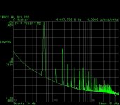
Lowering the LED current from 350mA to 50mA cured the solar cell noise problem (350mA was indeed uselessly high); I assembled last night another board with the old Rohm 2SB737/2SD786, the lowest noise transistors I have ever seen (designed for low noise, of course) for a fair comparison to the ZTX devices. Results are attached. This time the overall gain (DUT 24dB + measurement amp 60dB) is 84dB (or about 16,000).
While the ZTX devices have a slightly lower noise (280pV/rtHz, consistent with the reported lower Rbb) they suffer by having a much higher noise corner frequency. The Rohm devices (Rbb=2...4ohm for the pnp and 4...6ohm for the npn according to the data sheet) delivered 350pV/rtHz but are almost perfect in this respect. Very little on top of the expected 1/f noise. And actually the square ratio of Rohm/ZTX noise (1.56) matches pretty well the ratio of Rbb in these devices.
Attachments
Last edited:
The y axis is different ! (ZTX -80 ... -110 dB, 3dB/div - Rohm -60 ... -110dB, 5dB/div).
If plotted at the same scale, ZTX is clearly superior.
At 100 Hz, ZTX is at -102 dB while Rohm is at -95 dB
If plotted at the same scale, ZTX is clearly superior.
At 100 Hz, ZTX is at -102 dB while Rohm is at -95 dB
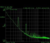
Noise at flat is in the upper right corner, in uV/rtHz. Divide the numbers by the overall gain and you'll get the input referred noise (at flat). 1/f noise is higher for the Rohm, but the noise corner frequency is much lower. At 500Hz the noise is about the same in both, at 1KHz the Rohm is slightly better. Expectation is to have the lower flat noise (the ZTX) to have lower noise at all frequencies compared to the Rohm.
Last edited:
To add insult to injury, something like the DeBroglie will not work at all on the bench; I am surprised it works even in simulation. The LT1028 op amp is open loop at DC; the drop of the input bias current (25nA) on the 22k resistor (about 0.5mV) multiplied by the open loop gain of 30*10^6 is large enough to bang the opamp output in the power supply rails. And the feedback loop is not compensated, C2=1nF is not good enough, for a closed loop gain of about 20dB this thing can be stable only by pure coincidence.
Same comment applies to the Heisenberg II and others, out of the versions with op amps only the JJ Thompson looks like a sensible design that has any resemblance to something that could work on the bench.
Agreed. They are OL at DC. The fix is to add a resistor across the comp cap ie from OP to INV input the value will be between 100k and 1 MEG.
Agreed. They are OL at DC. The fix is to add a resistor across the comp cap ie from OP to INV input the value will be between 100k and 1 MEG.
This has even more impact on the feedback loop compensation (or lack, thereof) though.
Noise at flat is in the upper right corner, in uV/rtHz. Divide the numbers by the overall gain and you'll get the input referred noise (at flat). 1/f noise is higher for the Rohm, but the noise corner frequency is much lower. At 500Hz the noise is about the same in both, at 1KHz the Rohm is slightly better. Expectation is to have the lower flat noise (the ZTX) to have lower noise at all frequencies compared to the Rohm.
The ZTX is lower for all frequencies! Yes, at 1 kHz and up the graphs are both quite flat and the cursor sitting at 5 kHz displays the corresponding level with lower noise for the ZTX and wich fits perfectly the lower base resistance.
For the lower frequencies where the graphs starts to climb up, it only looks higher as both your graphs on the Y-axis start at -110dB but ZTX goes up to -80dB while the graph for Rohm goes up to -60 dB. So, there is a different span: 30 dB for the ZTX and 50 dB for the Rohm resulting in different dBs per division on your analyzer. If you determine the output levels for various frequencies you will see that ZTX is significantly better. As said, at 100 Hz ZTX has about 7dB less noise level and at 10 Hz the difference is already more than 20 dB (about -90dB noise level versus -65 dB)
Not at 1-2KHz. I'll redo the measurements at the same scale for a more visually entertaining version. Meantime, see the noise corner frequencies for the two, the intercept does not depend on the chart scale (or the absolute values of the noise), the ZTX is clearly higher (also more difficult to interpolate a straight line, denoting some contribution of another noise source, likely some G-R).
At 100 Hz (mostly 1/f noise) or lower the ZTX appears indeed better, no debate here. The only comment is that the 1/f noise absolute level is hardly a good way to characterize bipolar devices, since it can be highly variable, from device to device and batch to batch (it's mostly related to process cleanliness, as much as the G-R noise). I would be very surprised if the shape at LF would be consistent for both the ZTX and the Rohm. The flat noise is relevant, and yes, I was expecting the ZTX to be slightly better.
Let me put it this way: the ZTX (1 sample) looks overall as having slightly lower noise (280pV/rtHz vs. 350pV/rtHz), but the Rohm (1 sample) is closer to what I would expect for the noise shape and noise corner frequency from a low noise bipolar transistor. But most likely, none of these would matter for audio, although the lowish beta of the ZTX would make it not recommended for all medium and high output MC cartridges (having higher impedances compared to a low output MC cartridge), since the input current noise is significantly higher.
Last edited:
Intriguing and I'm possibly misreading something but your measurements seem closer to the ones linked earlier in this thread than H&H results which, at 10mA seems to put the 1/f knee around 50Hz whereas at 25mA its IIRO 150Hz. At the 5mA you are using the Rohm should be slightly quieter or at least neck and neck, but the 1/f shouldn't be like that.
Certainly if obtanium (of if you have a stash) the 2SD786 is the choice.But for those of us without and a fetish for bipolar MC stages (and some daft low Z MCs)...
Certainly if obtanium (of if you have a stash) the 2SD786 is the choice.But for those of us without and a fetish for bipolar MC stages (and some daft low Z MCs)...
- Home
- Source & Line
- Analogue Source
- Richard Lee's Ultra low Noise MC Head Amp