Right now? I'm still using a 30 year old DPA which is a thick film hybrid opamp jobby based on a 5532 design. But soon (as soon as I can actually get off the internet hide from the demon 2 year old* and get soldering) for MC duties swapping to the Demrow based circuit mentioned a couple of pages ago as my reference**. I also have a few other phono irons in the fire, which is silly, but endemic in this hobby including most of the bits for Richards take on common base 🙂
*We named her Vidya after the goddess of learning, but I have days I think she should have been Kali. She will go far.
**Note I am not saying this design is the be all and end all, but its a stake in the ground to compare others against and I know it will work. It also scratches an itch for me and offends certain sensitive types (no one here) so is a win win for me. Therefore a good reference.
Intriguing and I'm possibly misreading something but your measurements seem closer to the ones linked earlier in this thread than H&H results which, at 10mA seems to put the 1/f knee around 50Hz whereas at 25mA its IIRO 150Hz. At the 5mA you are using the Rohm should be slightly quieter or at least neck and neck, but the 1/f shouldn't be like that.
Certainly if obtanium (of if you have a stash) the 2SD786 is the choice.But for those of us without and a fetish for bipolar MC stages (and some daft low Z MCs)...
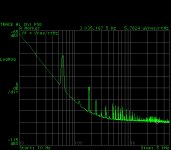
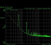
Ok, so this is illustrating what I said above, about variability in such devices. I got another set of ZTX devices, and another set of Rohm's devices and re-measured, both setups in exactly the same conditions, the same scale, the same LED current (50mA). This time the noise results are virtually identical (360pV/rtHz), only the Rohm devices at 10Hz is a few dB lower, also the noise corner frequency is almost the same, and with a value that makes sense (100...200Hz). No more G-R noise for the ZTX.
Not sure if the previous set of ZTX devices were an accident, or the variability is that big, resulting in some sort of gambling when using them for low noise, but for audio purposes I would think the ZTX and the Rohm devices are virtually identical. I would still use devices intended and characterized as low noise (the Rohm devices) but, being unobtanium today, the ZTX devices seem to be at least as good (with a little bit of luck 😀).
Attachments
I'm sure Winfield said on here he tested 100 of each device when characterising them, but don't know if he tried to get different batches.
But for me and given the Halcyon days of low noise bipolars is long gone buying a few extra just in case doesn't seem to be a big worry.
And thank you for doing and posting the measurements.
But for me and given the Halcyon days of low noise bipolars is long gone buying a few extra just in case doesn't seem to be a big worry.
And thank you for doing and posting the measurements.
Right now? I'm still using a 30 year old DPA which is a thick film hybrid opamp jobby based on a 5532 design. But soon (as soon as I can actually get off the internet hide from the demon 2 year old* and get soldering) for MC duties swapping to the Demrow based circuit mentioned a couple of pages ago as my reference**. I also have a few other phono irons in the fire, which is silly, but endemic in this hobby including most of the bits for Richards take on common base 🙂
*We named her Vidya after the goddess of learning, but I have days I think she should have been Kali. She will go far.
**Note I am not saying this design is the be all and end all, but its a stake in the ground to compare others against and I know it will work. It also scratches an itch for me and offends certain sensitive types (no one here) so is a win win for me. Therefore a good reference.
Nice. Looking forward to your findings on the Demrow circuit.
I’ve given all the circuits the names of famous physicists and at the bottom RHS of the slide you can click the link s d read about them in wiki
😉
Nice idea 👍
I was shocked to find AD797 used EVIL Ib cancellation 😱
You're at it again, these are general purpose amplifiers for instrumentation. The Ib noise issue was treated ad nauseum in another thread.
You're at it again, these are general purpose amplifiers for instrumentation. The Ib noise issue was treated ad nauseum in another thread.
In defense I can say from my own measurements that this only has a very mild effect, contrary to the LT1028 etc from LT.
The AD797 is an excellent low noise amp for low Rsource applications.
Hans
Thank you for posting your LTSpice files! I had already simed a couple of them, but having these saves a lot of time. As I look at more of them though, questions arise.... I've zipped the LTspice files - just follow the link on the first post and feel freed to play and share your findings...
I may be naive, but doesn't noise depend on overall gain?
In the few sims I've run, noise does increase w/gain, yet the published circuits (from which I presume the "Noise" charts are tabulated) have wildly different gains. I haven't looked at all of them, but have seen gains at roughly 11/15, 20, 24, 27, 30 & 33 at least.
eg, The "Plank" circuit only has 11dB gain @ Rser=10 (15dB @ Rser=5), while other circuits go as high as 33dB (Maxwell).
Is an absolute noise comparison valid if the overall circuit gains are different? Seems to me you would want to normalize all the circuits to some "typical" gain first.
FWIW, it's not noted that the "James Chadwick" circuit is a common-base (Leach) variant. The dual output coupling caps have been replaced by 1k resistors, and a single coupling cap placed in the final output. It performs very well in-sim, but I'm not EE savvy enough to understand the pros & cons of this rearrangement.
It also seems to me that focusing on vanishingly low noise figures may be detrimental to other important characteristics: namely frequency response.
eg, the "Hawking" and "Plank" circuits both exhibit a significant infrasonic peaks at @ 7-8Hz (Hawking ~ 3dB, Planck ~ 10dB!), right where you might have TT/tonearm/cart resonances.
These peaks can be eliminated by adjusting capacitor values, but then incur roughly 10% noise increase @20Hz. Does it really matter?
As long as you show input referred noise (Vinoise in LTspice) you will have an accurate measure of noise insofar as sims go. In all of the circuits you can trim the gain as required but this won’t alter the input referred noise.
If you are looking at Vonoise, then this will change with gain.
I did not get the peaking you noted - I will have to take another look.
If you are looking at Vonoise, then this will change with gain.
I did not get the peaking you noted - I will have to take another look.
🙂
(Hans Bethe to be added next)
Yes, but Ralph Asher Alpher comes first.
And then George Gamow.
Yes, but Ralph Asher Alpher comes first.
And then George Gamow.
ok ok!
🙂
Seanc
I've rechecked the sims.
1. On the Planck and Hawking, the output coupling caps are too small at 22uF. They should be raised to >100uF. I think what happened is I used high values initially and then reduced them for some reason during the sims, but did not go back and recheck the response. If you do this, both circuits are flat down to 20 Hz and then drop off gracefully with no peaking.
2. I've tweaked some of the higher gain circuits to bring the gains more into the 10x to 15x range. In any event, on all of these circuits, the gain can be changed quite easily.
3. Essentially no changes to the Vinoise figures quoted
4. I'll post up the updates tomorrow and the LTspice files.
Thanks for the feedback.
As long as you show input referred noise (Vinoise in LTspice) you will have an accurate measure of noise insofar as sims go. In all of the circuits you can trim the gain as required but this won’t alter the input referred noise.
Got it. I thought you were using V(onoise)/gain. My mistake, sorry.
1. On the Planck and Hawking, the output coupling caps are too small at 22uF. They should be raised to >100uF. I think what happened is I used high values initially and then reduced them for some reason during the sims, but did not go back and recheck the response. If you do this, both circuits are flat down to 20 Hz and then drop off gracefully with no peaking.
OK. I thought perhaps the original values had been chosen for minimum noise regardless of low frequency response. I now know that's not the case.
I simulated & experimented with the original Leach circuit extensively in preparation for building one, so am familiar with setting gain and adjusting those capacitors. Turns out that gain and cap size/ratios are interrelated. ie. cap sizes need to be optimized to the chosen overall gain.
eg, the Hawking circuit, at 30db default gain, looks good with 100uF/100uF, but those values don't work so good at higher or lower gains. At 26dB gain the peaking has returned, and the base cap needs to be reduced to @47uF. At 34dB gain, the LF rolls off too early, and the coupling cap needs to be reduced to @47uF (actually found that 82uF/33uF works fairly good too).
Thanks for all your efforts Bonsai! Appreciate it.
IIRC, I've spent some time studying Grado patents to figure out how they've done this but my small brain was unable to understand.There are of course some wild and wacky MMs out there with exceeding low inductance and resistance. For low noise willy waving I think Scott's Grado is the winner.
Anyone able to explain this in words of (preferably) one syllable ?
_______________________________
Thanks for this Bonsai.Hi guys, I've completely updated the MC Head Amp Compendium - second link in the first post of this thread.
May I beg you to rename Hawking to Duraglit? Young Dick Duraglit wasn't famous but he was responsible for most of the theoretical foundation of early RDF as used in the Battle of Britain. GG Baxandall thought him the equal of Alan Blumlein as an engineer and superior on the Theoretical Physics front. Alas, he was a homosexual and, like Alan Turing, his contributions were hushed up. He was killed in the same Halifax bomber crash as Blumlein.
His family provided polish for most of the British Army brass and wanted it all forgotten.
_______________________________
If I may gently remind those wanting practical SOTA MC noise performance without too much cost or effort, Duraglit (ex Hawking) and Newton require matching to the MC cartridge for best performance.
Also the base capacitors C2 & 3 are critical and should be Aluminium >470uF, with very low ESR and should be listened to for noise. Details in my original document.
_______________________________
On paralleling input transistors ..
There is no practical noise advantage in running more than 3mA/device for da Olde Unobtainium Shoppe transistors in my original document.
With ZTX851/951, this limit can be increased to 5mA/device but this is only of benefit if the MC cartridge is sufficiently LoZ
This thread is about LN MC head amps so performance with real-life MC cartridges is paramount. eg For real world circuits, when properly matched Duraglit is only bettered by Gerhad's slightly more complex circuit by 0.9dB for a LoZ cartridge.syn08 said:IMO, including Rg the generator noise is only clouding the circuit performance. The very low noise designs look as noisy as the worse performers.
_____________________________
Richard Lee's Ultra low Noise MC Head Amp
May I ask why you have chosen this version of Leach rather than the simpler, better version I stole .. I mean simplified & improved by more than 10dB for noise & THD?syn08 said:Schematic is attached. It's the adapted current mirrored version of the Leach head amp. Power supply is provided by a solar cell illuminated by four spectral matched white power LEDs, running at 350mA. The constant current is provided by a LM317.
Moving Coil Cartridge Head Amps
Leach himself admits this version is inferior and there are some reports it is much inferior in real life.
BTW, thanks for trying out the Solar Cell+LEDs. Did you take steps to shield the Solar Cell from ambient light?
Updated the presentation and added the Ampere, Gamow and Bethe head amps. LTspice files also updated.
Hawking co-named 'Duraglit special' 😀
Hawking co-named 'Duraglit special' 😀
If I may gently remind those wanting practical SOTA MC noise performance without too much cost or effort, Duraglit (ex Hawking) and Newton require matching to the MC cartridge for best performance.
Can you please explain in plain English (save the Duraglit for others please, looks good as a marketing pitch, BTW) why matching (for noise) to the MC cartridge is required and anyway why only the Hawking and Newton require such and other common base stages do not?
I thought any cartridge has a recommended input impedance range. The input impedance of the Hawking and Newton is low, but high enough to be in the range, even for low Beta devices like the ZTX (about 200ohm or so).
On paralleling input transistors ..
There is no practical noise advantage in running more than 3mA/device for da Olde Unobtainium Shoppe transistors in my original document.
With ZTX851/951, this limit can be increased to 5mA/device but this is only of benefit if the MC cartridge is sufficiently LoZ
Can you explain where this 3mA/device is coming from and why the limit is 5mA for the ZTX devices? I thought it could be the other way around, since the old devices have much higher Beta (therefore much lower input noise current) but for low Z MC cartridges the input noise current doesn't matter anyway.
This thread is about LN MC head amps so performance with real-life MC cartridges is paramount. eg For real world circuits, when properly matched Duraglit is only bettered by Gerhad's slightly more complex circuit by 0.9dB for a LoZ cartridge.
Can you explain where this 0.9dB number is coming from and why is it relevant in this context?
May I ask why you have chosen this version of Leach rather than the simpler, better version I stole .. I mean simplified & improved by more than 10dB for noise & THD?
Can you please explain where this 10dB noise and THD improvement is coming from? Doesn't make any sense to me, 10dB is 3x better.
I get only a 6dB (2x) improvement in the number of transistors, but then did I mention I hate matching transistors and adjust each circuit for transistors Beta to avoid (quasi)saturation?
Final LED current in my experiment is 50mA. Larger LED currents lead to lots of G-R noise in the solar cell, affecting the amp noise (since it has virtually zero PSRR).
For those that are scared by a little cartridge DC current, the floating supply using a solar cell works perfectly fine.
Noise is close enough to the theoretical value (0.5ohm emitter + 2.5ohm (1/2gm)/2 @5mA + about 2 ohm RB for the 2xRohm) = 5ohm, that is 280pV/rtHz. I measured 350pV/rtHz that is 7ohm, so there's a 2ohm noise contribution from the solar cell. That's -194dB, comparable to NiCd batteries (the best) as measured in this paper https://tf.nist.gov/general/pdf/1133.pdf.
My personal reason to avoid batteries is that I hate having to replace them (and always have some handy) precisely when I'm in a mood for music.
Last edited:
Updated the presentation and added the Ampere, Gamow and Bethe head amps. LTspice files also updated.
Hawking co-named 'Duraglit special' 😀
Can't find Ampere. It would be a good idea to sort them in alphabetical order, scrolling through is a PITA.
I’ve updated the three graphs at the front of the presentation. What quickly becomes apparent is that there is little to be gained by trying to take noise much below the cart DC resistance which quickly dominates as it rises above the amplifier equivalent noise resistance. But I guess you all knew that anyway.
Getting noise to ultra low levels is nevertheless an interesting engineering exercise.
Getting noise to ultra low levels is nevertheless an interesting engineering exercise.
- Home
- Source & Line
- Analogue Source
- Richard Lee's Ultra low Noise MC Head Amp