Thanks for your preliminary calculations. Yes accordingly to general calculations, the moving mass should be a max of 80gr.
I don’t know how that’s achiveable. If the shaft can be at least 60-70gr plus I assume the magnisium armwand to be not less than 50gr.
On top of that we have to consider the housing that joins the wand with the shaft that is a solid piece with the shaft for the counterweight maybe another 10-15g, plus counterweight itself can be another 10g or more?!
How can it all that be 80gr or less? If I add up not including any foam for dampening that can be around 200gr for the full moving mass.
Do you think I am missing something?
If this is the case 200gr will definitely be too heavy for most cartridges.
The total mass of Kuzma airline is 80 g, too. No. I didn’t copy theirs. As I said before, I have no idea how they did that. Comparing their arm to my latest arm, theirs has more parts than my arm.
My latest arm is 89 g which is 9 g over my designing goal, 80 g. I look at my arm, it is still possible to reduce its total mass, but I am not going to do that since everything is fine except its cartridge/arm missed my goal, 9-10 Hz. It is 7-8 Hz now.
I have done many different versions. The heaviest version was 190 g. It worked with low compliance cartridges, such my Denon DL-103 and Koetsu. A heavy mass arm enhanced bass greatly. Personally, I like heavy arm. However, it is not desirable to have such heavy arm. It will have negative effect on track ability. The heaviest arm among my three arms I have now is about 175 g.
For a medium compliance cartridge as Goldfinger, I wouldn’t advise to build an arm over 110 g. A 110 g arm will work for sure, but it is not ideal.
Does anybody have any suggestion as to which shop I can contact that produces precision hollow shafts maybe in titanium?
There are two things you need to think ahead. 1st, you need find a stock metal tube which has ID 3/8” and at least 3/4” OD so someone can grind it down to 1/2” OD. It is possible to ask someone to make one for you. Secondly, you need to plan ahead how to make the rest of parts. I wouldn’t advise to use EMT arm wand because it may excess the limit of total mass and I feel the head shell is not heavy as I may want to. Unfortunately, I don't have any information regarding machine shops. So, I am not able to help.
I would like to make the wand in 1/2” titanium. Here is a link to get custom cut length.
Buy Material Online
If the wand is 6”, total mass will be 22 g.
Moreover it was estimated a length for the shard of 15” but if we go for one bushing next to the other, similar to the proscenium tonearm that has the counterweight on the extreme left side of the shaft, this arrangement requires a shorter shaft than having the two bushing spaced apart and the wand in between them.
Now my question is which arrangement is technically preferable, the one used on
The proscenium tonearm or the one used by the Chinese guy at post #81?
If you want to make Walker Audio’s style, the length of shaft is at least 8”. It will greatly reduce the mass almost in half. You still need two 1/2” air bushings. I saw some people use just one air bushing for this kind of moving shaft arm. I am against to do so.
In theory and from construction aspect, I think the implementation by the Chinese guy is better than Walker audio kind. However, the Chinese guy’s implementation may make whole arm a lot of complicated.
Your main challenge, in my opinion, is how to get the shaft done no matter what kind of arm you are going to make.
Jim
Last edited:
Thanks Jim.
I have mentioned previously that I had already ordered the EMT wand which I just have receiced today.
It is the magnesium version and weighs only 21.8g.
I was very pleased to see how light it is. Beside that, it is a one formed piece tapered magnesium wand so the headshell is not a separate piece. This makes it for an extremely stiff build.
I will be using 2X 1/2" air bushing so I will probably take your offer later on which we can discuss in private in fact can you please email me with how much you want to charge for the two air bushings?
However first though like you said I need to source the shaft or this build won't be even possible at which point I would have to circle back to the moving bushing design.
Given the small options I have around i will probably have to give a Chinese manufacturer a chance.
I want to see if the shaft can be made in titanium, this would cut the weight down significantly and increase also rigidity. Moreover I will go for the walker audio arrangement to further cut weight down due to the shorter wand as you suggested.
I will consider a shaft of 8" or around that number. Actually, I probably have to start sketching something to start assigning some exact dimension for the shaft.
The shaft will have some foam inside to damp vibrations and I will close the ends with some delrin cups that I will have custom machined.
For CNC at this point I will use the same shop that will make the shaft.
I will start looking around and once I have found something I will post here to get some feedback.
EMT arm is much lighter than I thought.
Once you have done some drawings, please let us see. I would like to know your construction plan. Keep in mind. It is nice if the center point of air bearings should be on same level as LP or lower.
I don't like the damping tough of Walker Audio since it can't damp inertia vertically. I would suggest to change it.
Jim
I don't see any dumping on the walker audio. I would probably have a similar design as Kuzma but the little paddle goes straight down from the housing for the wand to the long tank.
I will try to sketch something up now and post tonight.
Yes the magnesium armwand is really light. I have another roughly 60g to spare between shaft and the joining piece and counterweight, which is very, very tight to make.
I will try to sketch something up now and post tonight.
Yes the magnesium armwand is really light. I have another roughly 60g to spare between shaft and the joining piece and counterweight, which is very, very tight to make.
I am posting this site for records they make precision ball bearing linear shafts and hollow bars but they are all steel.
L1769 - Thin Wall Ceramic Linear Bearings | Automotion
Has anybody ever given a though to these kind of bushings instead of the air bushing? Just curiosity.
I am sure they are not as free floating as the air system, correct?
L1769 - Thin Wall Ceramic Linear Bearings | Automotion
Has anybody ever given a though to these kind of bushings instead of the air bushing? Just curiosity.
I am sure they are not as free floating as the air system, correct?
These bearings are not designed for frictionless tight tolerances that tonearms require and need.
You would do well to find an ET -2 arm or An old Maplenoll air bearing/air platter and rework one of those.
You would go much farther and get great results than trying to roll your own unless you want to learn the hard way and enjoy the learning curve,.,
The Walker is nothing more than a fancy Maplenoll design and it’s obvious they owned one at one time
They simply polished the rough edges and charged extreme money for the bling.
Worked out well.
Regards
David
Thank you David for your comment.
First of all I didn’t know the walker audio was an identical copy of the maplenoll.
However for as much as I don’t particularly like the guy behind walker audio, I must say his arm is reported to be the finest linear arm in the market by many reviewers.
With that said if he implemented much more precise bearing structure this can easily jack up the price compared to the original design.
I do agree though he is taking big advantage of many people that would pay $$ for a copycat.
My understand so far, the major difficulty is to produce a precision bearing and shafts as super has already shared his knowl she of his long development which without it it would be impossible for me.
Don’t get me wrong I truly understand there are a lot of more complications in designing a functional structure that will allow adjustments and that everything works as intended and I am sure there is a learning curve.
If I wanted to buy the ET2 or the Rockport I could certainly save up and buy at one point but at this point I am interested to make one with the help of knowleadgeable people here. So if I make it then other people can attempt to make it as well.
Also, if you have seen post #81 people simply used two bearings and a precision shaft and obtained a better result than the ET2 for example.
Maybe I should explore that option instead of the walker topology at least it seems a bit original as other manufacturers have not used that method yet.
If you could kindly offer your skilled contribution along with the other users here I am willing to go through the learning curve and to pull through this project.
Thank you!
#81
First, the horizontal mass is unnecessarily too high because of the wrong headed use of 2 bearings spaced apart.
The second issue is coefficient of expansion and the possiblility of a sticking air bearing at that distance based on dissimilar mounting materials and getting it adjusted and stable under all temperature differences.
A long arm shaft like that requires a centerless grind of perfect dimesions more so than a shorter version that moves less
I not saying it doesn’t work, it’s just impossible to get low moving mass this way.
And it would only work with ultra low compliance Mc,s , unless you want severely pumping woofers at warp frequency’s with other cartridges
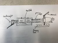
Your hand drawing would be better but also more complex and again adjusting both would be a challenge and really over complicated. It looks like an ET BTW.
The early Maplenoll had 4 holes (8 total) near each side of the pressure tube it slides in.
The ET -2 has 5 holes of high tuberlance on each side, so 10 holes that in the end pressurize the whole tube length in combination
This allowed a shorter pressure tube and thus less length and horizontal mass unlike the longer Maplenoll design with less pressure holes and longer air bodies
We’re talking 3 psi for the ET-2 and Maplenoll to start working and only about 10 psi at their best sweet spot.
Walker just ups the pressure in the basic same design.
The only down side to the excellent New Way or Versa design is the mandatory high pressure/small surface area AND the air tube friction issue since it must move by the needle unlike the others that only deal with wires and low pressure.
They both have their quirks and features
I will post my version I built using Maplenoll parts back in the early 90,s later on to help you narrow down and simplify
With air bearing TT,s it’s best to think in KISS principals for the best outcome.
Regards
David
First, the horizontal mass is unnecessarily too high because of the wrong headed use of 2 bearings spaced apart.
The second issue is coefficient of expansion and the possiblility of a sticking air bearing at that distance based on dissimilar mounting materials and getting it adjusted and stable under all temperature differences.
A long arm shaft like that requires a centerless grind of perfect dimesions more so than a shorter version that moves less
I not saying it doesn’t work, it’s just impossible to get low moving mass this way.
And it would only work with ultra low compliance Mc,s , unless you want severely pumping woofers at warp frequency’s with other cartridges
Your hand drawing would be better but also more complex and again adjusting both would be a challenge and really over complicated. It looks like an ET BTW.
The early Maplenoll had 4 holes (8 total) near each side of the pressure tube it slides in.
The ET -2 has 5 holes of high tuberlance on each side, so 10 holes that in the end pressurize the whole tube length in combination
This allowed a shorter pressure tube and thus less length and horizontal mass unlike the longer Maplenoll design with less pressure holes and longer air bodies
We’re talking 3 psi for the ET-2 and Maplenoll to start working and only about 10 psi at their best sweet spot.
Walker just ups the pressure in the basic same design.
The only down side to the excellent New Way or Versa design is the mandatory high pressure/small surface area AND the air tube friction issue since it must move by the needle unlike the others that only deal with wires and low pressure.
They both have their quirks and features
I will post my version I built using Maplenoll parts back in the early 90,s later on to help you narrow down and simplify
With air bearing TT,s it’s best to think in KISS principals for the best outcome.
Regards
David
Last edited:

The Walker is nothing more than a fancy Maplenoll design and it’s obvious they owned one at one time
They simply polished the rough edges and charged extreme money for the bling.
Worked out well.
Regards
David

initial sketch for the concept
I can't comment too much since it is a rough sketch. But I need to point out that you need to leave some space between two air bushings. Compressed air may make noise if two bushings are too close to each other. My suggestion is 1". Leaving space between air bushings will restrain the movements of the shaft better.
Jim
Hi David,
I have never look inside of ET arm. Are there any air grooves in the air bearing? If there are no air grooves, high air pressure may cause shaft vibrations due to uneven distribution of air. A long custom made porous air bearing with air chamber in middle will be perfect.
Jim
I have never look inside of ET arm. Are there any air grooves in the air bearing? If there are no air grooves, high air pressure may cause shaft vibrations due to uneven distribution of air. A long custom made porous air bearing with air chamber in middle will be perfect.
Jim
No
What the arm tube slides in is a thicker tube held in with 2 - O rings
Near the ends of this tube are 5 holes that are threaded.
A small set screw (the kind that locks a volume knob for example) is run down into each hole and stops just before the sliding air tube.
It feels like a metric screw going down into an American thread pitch where it just stops with slight resistance
Each set screw has its male thread slightly rounded off so no sharp thread points
Allowing air to circulate down the thread gap for turbulence at the air gap junction point
Regards
David

Thanks for the photo, David!
I understand it now. I am wondering why they use set screws as air supply holes. Perhaps they didn't have the technology to drill very small holes on the internal wall at that time. So, I guess the set screws can be used to control air flow. I am also wondering if small holes may do a better job if each end has at least 8 holes around the internal tube. Another reason these arms can't use high pressure because the o rings may be able to hold high pressure.
Jim
Last edited:
Sorry you can see I am a completely newbie as I have almost no clue what I am looking at when you say set screws creating air turbolence.
First of all, to see if I understand correctly, I assume the gray/silver arm to be your latest or the one you are currently using, correct?
Is this built using ET air bearing shaft and bushing parts?
How heavy is the shaft? Have you measure it?
Is the air bushing you are using a custom design from ET or do you think it could be had?
Would it be equally good to use two new ways air bushing next to each other (with spacing as super is suggesting)?
In your latest design, the one with the armwand I assume, you have the counterweight on the same side as the armwand and not at the other end, am I correct?
I am still struggling finding a source for the hollow shaft.For some reasons, it much easier to acquire a precision solid steel shaft than hollow precision aluminum.
I was wondering, the Rockport arm has moving bushing design, but they run the pressure much lower than typical kuzma design and they declare to use a different type of airbushing, I have researched but can't find any clue that leads me to the type they are using.
Rockport is said to be the best tonearm in the market (at least for the linear arms). Do you have any idea what they could be using?
Also do you have any idea like super was suggesting, how it would be possible to get a longer airbushing with the air chamber in the middle similar to the one that ET uses?
Sorry for all these questions, like I said I am here to learn.
I can't comment too much since it is a rough sketch. But I need to point out that you need to leave some space between two air bushings. Compressed air may make noise if two bushings are too close to each other. My suggestion is 1". Leaving space between air bushings will restrain the movements of the shaft better.
Jim
thank you for the tip, increasing the distance will also increase the length of the shat thus the weight. It's very, very hard to meet the requirement for the weight.
Thanks for the photo, David!
I understand it now. I am wondering why they use set screws as air supply holes. Perhaps they didn't have the technology to drill very small holes on the internal wall at that time. So, I guess the set screws can be used to control air flow. I am also wondering if small holes may do a better job if each end has at least 8 holes around the internal tube. Another reason these arms can't use high pressure because the o rings may be able to hold high pressure.
Jim
That is Maplenoll in a nutshell for you! I guess their finest tool was a wood ax.

The level of soundquality, on the other hand , coming out of these (especially the Ariadne) was amazing. I was the importer of Maplenoll in Denmark for some years..
After having looked around it seems to be extremely complicated to find a stock hollow suitable shaft. It become even more complicated to find a specialty shop that will do one or two pieces and finally it's hard to reach the goal of 80-90gr total moving mass.
So after giving some more thoughts, for this project it is probably best to move forward with the implementation that super has done already on this thread.
Therefore, I will go for a 20mm air bushing from new way and I am looking around for high quality 20mm stainless steel shafts.
Fortunately, there are several options and manufacturers around for that.
OAV was originally suggested and makes very nice shafts. Also online it seems it is possible to get even better/smoother shafts.
For example I found this one that has a surface finish of 8RMS (OAV has 16RMS for example).
SM series Metric Linear Precision Shafting | Lintech
I will keep looking a little more. I wanted to double check with you since as I said I am newbie in the mechanical field and especially to interpret mechanical specifications.
Am I wrong or the specifications for the shaft here are extrmely good, or am I missing anything?
Thanks in advance for the help.
It seems to me it is a good find. Its tolerance is very good so the air gap will be even tighter. A tighter air gap means lower pressure with stiffer bearing. I am not sure about the surface. I would think it won't make too much difference. The price is good too. A 10" shaft is only $26.00. I would try it first. If it doesn't work, it is only $26.
Jim
Jim
- Home
- Source & Line
- Analogue Source
- DIY Air Bearing Linear Arm