
No it's not about just about the mass. The larger mass IMO is more difficult to excite into resonance and thickness of the polybento is needed to ensure the spindle to arm remains as rigid as possible.
My plinth is 80mm thick and requires 4 pours. This is thinner than some others, I know Bon's plinth is about 100mm thick.
When I pour the plinth I do it in small batches but immediately after each other, I don't wait for the resin to cure as this causes inconstant shrinkage I use between 0.5 and 1% catalyst depending on the weather. Too much catalyst and the plinth will crack.
Thank you. I'll post pics along the way. My first thought is to use an Al plate on the mold bottom to help dissipate heat. We'll see.
Right now my biggest worry is the arm attach height.
Don
I used a fan blowing directly on the resin.
My arm mounting surface in 18mm below the top of the plinth, this works for the EPA100 even with a platter 15mm higher than stock.
Hi Worrjon,
did you try before maybe a platter with the same weight as the original platter plus rubber mat?
Rolf
I'm not sure what you mean.
I did use a stock platter with original mat. I also used a stainless steel platter with original mat, which out performed the OEM platter.
I used a fan blowing directly on the resin.
My arm mounting surface in 18mm below the top of the plinth, this works for the EPA100 even with a platter 15mm higher than stock.
Great thank you. Did you build your mould to cast upside down or right side up. I would think upside down would control the finished surfaces better.
Also, I think you and Bon are continuous cast across the bottom whereas the Technics plinth has a giant hole. Is that correct? The motor case actually sticks below the bottom of my obsidian plinth just a bit. This is all different geometry though so I am guessing there will be 25 or 30mm of resin/bento across the bottom.
No cooling vents necessary?
Don
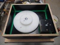
Yes it's cast upside down and solid except for the holes for motor, platter and tonearm.
The inserts I used are made from poly cutting boards and actually belong to Bon who loaned them to me. Platter insert is 323x30mm and motor insert is 154x24mm.
The green in the mold is Plasticine to prevent the resin leaking out. If you get the catalyst incorrect the Plasticine will melt. The mold id made of form ply this has a coating that nothing sticks to and is used in concrete forms.
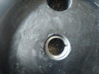
My plinth is smaller than Bon's and also has the hole for the bearing drilled through the plinth and I have an insert that holds the bearing rigidly as the motor is bolted down.
There is an aluminium ring under the motor and under the plinth. So the motor sits on the aluminium and is bolted all the way through the plinth
The inserts I used are made from poly cutting boards and actually belong to Bon who loaned them to me. Platter insert is 323x30mm and motor insert is 154x24mm.
The green in the mold is Plasticine to prevent the resin leaking out. If you get the catalyst incorrect the Plasticine will melt. The mold id made of form ply this has a coating that nothing sticks to and is used in concrete forms.
My plinth is smaller than Bon's and also has the hole for the bearing drilled through the plinth and I have an insert that holds the bearing rigidly as the motor is bolted down.
There is an aluminium ring under the motor and under the plinth. So the motor sits on the aluminium and is bolted all the way through the plinth
Attachments
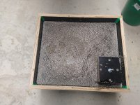
Don't worry we all stuffed up on the first plinth pour. I used too much catalyst 2% and it got too hot for the fan and cracked so badly it was binned.
the beauty of polyester resin is it's fixable mostly and if you end up with small cracks they can be repaired. My last plinth I dropped and broke the whole side away where the arm recess is this glued back with epoxy and is stronger than original.
So if it doesn't go right ask before you bin it.
Also I cover my plinths with fiberglass mat and then gelcoat tinted black. Others use bondo to fill and get the plinth level.
One thing to keep in mind the arm mounting surface needs to be parallel to the platter.
Last edited:
Did I ever mention when a new mold was built with the inserts in a mirror image of the intended arrangement? One of the pitfalls of casting upside down ... think things through carefully. Oh what fun was had with the sledgehammer.Don't worry we all stuffed up ...
My last plinth I dropped and broke the whole side away ...
geometry
I am working on my SP-10 plinth mould. I think it will be cast next weekend.
A lot of details so thanks for all the posts by Bon and warrjon. I want to double check a big picture item. Mine is a standard chassis mount. My mould is 92mm thick. The distance from she chassis finished edge, its resting point, to the bottom of the motor skirt is 54mm. I plan to cast a 62mm deep hole leaving 30mm across a solid bottom. My question is the virtually closed airspace between the chassis bottom and plinth that is only 8mm. I have really been thinking about providing 4 vent holes in the bottom. I think it will be plenty stiff and I shouldn't loose too much mass. Any comments about this.
Thanks,
Don
Don't worry about the vent holes there is not enough heat generated in the SP10 worry about them.
Only the motor dive transistors are heatsinked and they are fixed to the chassis top.
I would however add something between the bottom housing and the plinth to takeup the gap and damp the bottom plate.
Only the motor dive transistors are heatsinked and they are fixed to the chassis top.
I would however add something between the bottom housing and the plinth to takeup the gap and damp the bottom plate.
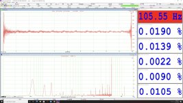
PSA: We've found the W&F calculation in MI to be suspect when measuring from motor FG (~100Hz). The numbers are bit more reasonable if you use a 120Hz LPF on the signal to keep MI from measuring above the fundamental.
To illustrate I redid the measurement here with the 120Hz LPF: The Incredible Technics SP-10 Thread. This Changed several of the measurements more than a tad, but some things still appear off. The plots are FM demodulated and you can clearly see significant issues at 0.55Hz, 1.1Hz, and 1.65Hz, making the reported 0.0090% RMS wow suspect.
We also see evidence that the filter ringing is part of the calculation, and is showing up in the spectrum. This isn't all the surprising with digital filters and a tool that was intended for test signals in the kHz range. Still useful, but you definitely need to be able to analyze the demodulated time and frequency domains plots to really see what's going on.
Attachments
matching mounting holes
Bon,
Re your post #1309 pics, what is your technic to get a perfect match for the mounting screws through the plinth into the chassis? Do you make a really accurate pattern? Not much room for error to get the match. Even more difficult with the R.
Thanks,
Don
Bon,
Re your post #1309 pics, what is your technic to get a perfect match for the mounting screws through the plinth into the chassis? Do you make a really accurate pattern? Not much room for error to get the match. Even more difficult with the R.
Thanks,
Don
- Home
- Source & Line
- Analogue Source
- The Incredible Technics SP-10 Thread