Partial response
Bon, Warrjon, pfarrell:
Thanks on acetone. My intent was to mount my EPA100 tone arm directly to the plinth. No armboard. The build is supposed to have the TA mount directly to the plinth at 18mm below the main surface. I could have this totally wrong but I won't know until I actually try to install it. Fingers crossed. The build is definitely single purpose however. Thanks for the acrylic backup plan. I am not looking forward to drilling the hole for the TA through this stuff. 25mm thick between surface and cavity. Grr....
Warrjon, I will. I will take pics and hopefully be able to put a ruler on it. I have put a straightedge on it and it is pretty flat but I got just a little sag at one corner. Guessing a couple mm. I will show you. My observations on my mould are,
Concept worked pretty well but I used 1/8in Al which is a little bendy. A really flat table is key to the hole thing. I tried to make up for mine by having 4 2x2in Al tubes which held it pretty straight. You can see only two of the tubes in one of the pull pics. My table is cr__. That will get changed on the next casting. Another reason for the tubes was to get ventilation under the mould. I believe it is possible to get it near perfect (less than a mill) across the whole thing. You probably understand better than I how to do this. I was really surprised how hot it got. Almost too hot to hold your open hand on it.
Note: I am going to paint my plinth piano black just to see how good I can do. My goal is to do the Kaneta style plinth somewhat in the style of the obsidian plinth.. In piano black. I wonder how many castings that will take.
pfarrell, I could use some good ideas on how to cast roundovers and tapers in the mold. You are really good with this stuff. Problem is it has to be accurate, and very smooth so with mould release there is no adhesion to the casting.
I'm excited about this project. Thanks to all.
Don
Don, I don't have any exact experience with the materials you are working with... but I do have a lot of concrete experience. I have a couple of thoughts. Inner small roundovers, say 1/8"-3/16" can be done with tube silicone and a 3/8" or 1/2" acrylic rod cut at 45 degrees as a "beading" tool. Fill a corner with silicone, run the beading tool in the joint, wait for it all to dry, and then peal off the excess. The beading tool will create effectively a zone of no silicone between the actual corner where you want a nice roundover (dimension is controlled by the size of acrylic rod) and the excess will easily peal off a sealed mold surface like melamine or sealed wood or acrylic. For unusual inner shapes, you could cover them in clear packing tape, being very careful not to create seams that will end up in the casting. Packing tape will actually cast in concrete, I've used this technique for making circular plugs covered in tape, basically as a mold release. Also, if you have any formica, you can cover any odd beveled flat shapes, possilbly even large inner roundovers with formica and contact cements. In a perfect world, if I were to make a mold for GFRC concrete for a plinth—which I have considered—I'd likely carve the whole thing out of a built up MDF block, make a mold of it, then used the mold (supported) to receive the concrete mix... Lot of work though. I think I would be challenged to "hear" the sonic differences between that and the Russian ply loaded with lead constructions I've made to date.... Next plinth will be for 2 arms—no arm boards. 12" and 10.5" setups respectively. You can also make a template for "inside" of the entire outer shape if you wanted 4 large round edges—stacking up 3/4" material to whatever height, then covering the inner surface with tapes or other release materials. Obviously this is a job for the router or CNC. Hopefully some of this is clear—it's hard to write descriptions of process.warrjon,
pfarrell, I could use some good ideas on how to cast roundovers and tapers in the mold. You are really good with this stuff. Problem is it has to be accurate, and very smooth so with mould release there is no adhesion to the casting.
pfarrell, you did great. Opened up my mind to new concepts that I can probably implement.
Thank you very much.
R,
Don
Thank you very much.
R,
Don
I could use some good ideas on how to cast roundovers and tapers in the mold. You are really good with this stuff. Problem is it has to be accurate, and very smooth so with mould release there is no adhesion to the casting.
I'm excited about this project. Thanks to all.
Don
IMO the best way to make a copy of the obsidian plinth is to build a buck from MDF as an exact copy. Cover it with 2 pack polyurethane varnish and sand ect to get a smooth surface. Then take a mold in fiberglass, there are heaps Youtube videos on how to do this.
The mold can be used to make a copy of the plinth. I would make the mold flat bottom and use inserts for the platter and arm.
Also 18mm below the plinth top is about right for arm mounting surface, that's what mine is. You can IMO use solid aluminium arm boards as aluminium has about the same acoustic impedance as the steel EPA100 base.
Last edited:
In the US—these guys are just incredible (concrete centric) both with DIY vids and products with a lot of the science already sorted: Trinic
They have a mold making kit....most of the same principles apply.
They have a mold making kit....most of the same principles apply.
Don,
Be prepared to throw away your drill bit. Bento/resin is unkind to tooling. I use a wood spade bit for the larger holes.
With the heat from the curing, I am surprised the Al plate did not sag more.
For the roundovers, I found a table router with a 1/2" roundover bit has always produced good results. Smaller radius rounders are less forgiving of imperfections and harder to prep and paint. Again, you will probably need to toss the bit after use. A table router is preferred to a hand held. The large mass actually makes it easier to control with slow and steady movement. With a hand held router there are too many variables in play for comfort and the dust collection is a problem.
Keep on with the updates. I am sure your progress will inspire others in this forum.
Always ready to advise.
Bon
I am not looking forward to drilling the hole for the TA through this stuff. 25mm thick between surface and cavity. Grr....
Be prepared to throw away your drill bit. Bento/resin is unkind to tooling. I use a wood spade bit for the larger holes.
Concept worked pretty well but I used 1/8in Al which is a little bendy. ....
I was really surprised how hot it got. Almost too hot to hold your open hand on it.
With the heat from the curing, I am surprised the Al plate did not sag more.
For the roundovers, I found a table router with a 1/2" roundover bit has always produced good results. Smaller radius rounders are less forgiving of imperfections and harder to prep and paint. Again, you will probably need to toss the bit after use. A table router is preferred to a hand held. The large mass actually makes it easier to control with slow and steady movement. With a hand held router there are too many variables in play for comfort and the dust collection is a problem.
Keep on with the updates. I am sure your progress will inspire others in this forum.
Always ready to advise.
Bon
In the UK when individuals have produced DIY Slate Plinths.
It has been reported that a cutting tool with a carbide tip, Jigsaw Blades and from recollection Boring Tools do not Blunt and can produce the required cuts in a refined finish.
Obviuosly not to a professional cut refined finish.
It has been reported that a cutting tool with a carbide tip, Jigsaw Blades and from recollection Boring Tools do not Blunt and can produce the required cuts in a refined finish.
Obviuosly not to a professional cut refined finish.
surprised
"With the heat from the curing, I am surprised the Al plate did not sag more."
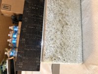
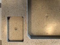
I think I got lucky. I checked flatness yesterday and the most out of plane I got was 0.5mm. That was at the back left corner. Anything else less was less than that. I put a light behind the straight edge so I could really see it. I don't know if I should even try to mill it. I think I will see how things go on the bottom and pick my poison for perfectly level.
I am totally excited about the TA recess. It is perfectly flat and level with the top surface at 19mm recess. Not sure how it grew from the 18mm mold. ??? The black markings in the corners is felt pen ink transfer off the mold that I had marked to identify the corners to mill.
Looking closely at the top surface, I am surprised it is as good as it is. And the corners and edges are in great shape. Nowhere to go but down from here. Better not drop it.
Don
"With the heat from the curing, I am surprised the Al plate did not sag more."
I think I got lucky. I checked flatness yesterday and the most out of plane I got was 0.5mm. That was at the back left corner. Anything else less was less than that. I put a light behind the straight edge so I could really see it. I don't know if I should even try to mill it. I think I will see how things go on the bottom and pick my poison for perfectly level.
I am totally excited about the TA recess. It is perfectly flat and level with the top surface at 19mm recess. Not sure how it grew from the 18mm mold. ??? The black markings in the corners is felt pen ink transfer off the mold that I had marked to identify the corners to mill.
Looking closely at the top surface, I am surprised it is as good as it is. And the corners and edges are in great shape. Nowhere to go but down from here. Better not drop it.
Don
Attachments

That's way flatter than mine was. Maybe the aluminium worked to sink heat away and prevent the plinth warping.
If all goes well, it is looking like some of the investigations carried out using exchange Platters, and Plinth Materials are to replicated by my friend and myself on the
SP10 MkII.
The exchange Platter that is to be a Phosphor Bronze Material will be able to be used on the variants designs produced.
As for a Material that measures similar to the PolyBentonite Resin Material in use for a Plinth, there is the alternative Material that is the Densified Wood 'Panzerholz'.
P'holz is already in use as a Plinth Material and both P'holz and Permali are readily available as Donor Material for the project.
There is also a opportunity and one that is of great interest to myself, and is now offered as a experiment to be produced, where a Kaneta Design is to be produced and coupled to a P'holz Plinth.
I am fortunate to have my friends support in producing these variants of the Stock Model, as their understanding of the requirements and their practicle abilities are of a extreme adeptness.
Also what will be another control measure, is that the Tonearm and Cartridges used for the assessments will be identical on all variants in use.
Fortunately there will be more than one Tonearm available, allowing for almost immediate A/B Listening Comparisons if prepared for.
The information within this Threads most recent evolvement has had a impact, created a curiosity and a motivation to participate in a R&D.
JohnnoG,
NICE! Please post lots. Just curious, do you have access to CNC to mill the Pholtz? I had a big debate amongst myself between Pholtz and resin/bento
and went with the casting because it was DIY. Writing the check would have been easier.🙄
R,
Don
NICE! Please post lots. Just curious, do you have access to CNC to mill the Pholtz? I had a big debate amongst myself between Pholtz and resin/bento
and went with the casting because it was DIY. Writing the check would have been easier.🙄
R,
Don
If all goes well, it is looking like some of the investigations carried out using exchange Platters, and Plinth Materials are to replicated by my friend and myself on the
SP10 MkII.
Do you have the capability of performing proper measurements? I love all the DIY work and seeing some truly impressive machine work, but thus far we're devoid of any meaningful relevant data, which would be very informative to have.
As said previously.
A opportunity to take part in somethig as described is very much dependant on the support from a friend,
who has Pre-Retirement Career in Machining and Electronics with a very high level of training.
Working with P'holz to produce the Plinth Design is not a restriction to the project.
I have taken on my usual role in such matters, I get all excitable and have supplied information that has generated a interest, I have declared myself responsible for offering a selection of Donor Parts for the project.
From this point on, I will be available to support when requested and will be a set of ears to support in the assessments of the variants SQ.
Whether there is an intention to produce measurement data, I do not know, but my friend does have electronic equipment available that 'might' have the capability to produce a data that is off interest to outside observers.
Measuring the finished designs could be already on the plan, but not made known at this stage.
As and when a Update can be offered, I will make it known.
Last edited:
Good luck with measuring the difference between platters, my qualifications are in electronics and metrology and worked in the field for over 40years, so I'm experienced with measuring very small signals. I have been unable to measure the difference between the OEM and POM platters. I don't use MI it's a toy, I use a calibrated HP signal analyser. The uncertainties associated with MI are unknown unless the system as a whole is calibrated you have no way of knowing what artifacts it adds or subtracts from the signal.
The simple way of detecting Wow.
Play a W&F tone and listen to it, if the LP is eccentric you will hear the pitch vary, we humans are very sensitive in this area to pitch instability from 100mHz up modulation on the 3kHz fundamental. Center the LP on the platter and listen.
Flutter is much harder to detect especially at low levels and to do properly needs an FM detector or a narrow band signal analyser.
I can clearly hear the difference between the OEM and POM platters but recording the same music at 96/24 the difference is inaudible.
Whether there is an intention to produce measurement data, I do not know, but my friend does have electronic equipment available that 'might' have the capability to produce a data that is off interest to outside observers.
Measuring the finished designs could be already on the plan, but not made known at this stage.
As and when a Update can be offered, I will make it known.
Appreciated. If he's interested and wants to make serious attempt at it there are many folks who'd be happy to help. It's not easy - certainly not a "point and shoot" task.
I think it is a casr of 'Watch this Space' the intention is not in any way to attempt to surpass and of the Investigative Projects that have been undertaken.
There is an opportunity to participate in a similar approach, as the Parts are available, along with the Adept Skills required.
Apart from the work done on the SP10 MkII that has been covered on this thread, another very recent stimulation has been a Project that started as one being done on my behalf and the project migrated to another, as a result of their not having a TT to use, and my having too many TT's to use.
The individual who has received the finished work Now Has Two Sony TTS 8000's, both in P'holz Plinths and has reported that the Variant with the New Bearing design is much improved over the OEM Model.
In their view, the quietness of the TT, is immediately noticeable, as the earliest reports.
This was a journey into the unknown for a TT, using Modern Design Methods that are known for their Valued Properties, and it will be good to track the user reports as they progress.
The SP10 MkII in use as planned, will be a New Experience to be undertaken, the methods to be used are already backed up as a worthwhile investigation by the works already achieved on this thread.
If you can surpass the performance of the mods detailed in this thread I say go for it. I for one am always open minded to mods done by others. Some of the mods I have done the ideas have come from other people modding Lenco's Garrard's etc.
Just keep in mind to always follow the well established laws of physics. Other things I would suggest is to look at what the top end of town TT manufacturers are doing, the likes of Continuum, SAT and Clearaudio etc, etc.
On another note one of my SP10's has a damaged bearing sleeve, it has a score mark probably from running dry at some point in its life. I have machined a new bearing sleeve in PTFE (as I had some) although not perfect I bored the bearing which required the motor to be turned over in the lathe which is not ideal as it's impossible to align the top and bottom bearing sleeves perfectly, even 0.001mm runout with this tolerance binds the spindle.. I have ordered a 0.2812" reamer which I'm hoping will fix the alignment issue.
Hi Warrjon
Our association with a stimulus to play with TT's has come from similar backgrounds.
I had a Garrard 401 and after a period of ownership it was treated by a Martin Bastin for his Bearing and TT Work.
This eventually ended up in a 9 Stone Granite Plinth.
After many years of ownership the Lenco Direct Drive become of interest and I ended up with basic models and a PTP Solid 9.
Lenco Heaven has been a regular visited Forum and much has been learned from here on how to improve on a structure for a TT as well as the finest of tuning for the mechanics.
This has overspilled into a usage of Japanese Vintage DD's hence the SP10 MkII in daily use having been overhauled by a very adept individual.
Then the same individual took on my wish to have the TTS 8000 issues resolved,
this progessed into a Bearing Overhaul and Modernisation commenced as a result of a deteriorated Bush in the Housing and the additional lessons learnt during the Deconstruction.
Now with your stimulus and those that are following, the opportunity to try out the methods you are using and share in your findings are another journey of discovery.
Fortunately much of the needed materials are already acquired, and could be referred to as a Spare Material.
I do believe the Tooling Needed is available in house, so no need to out source any work.
The Time Allocation will be the much needed commodity.
I am myself a passenger now, and will only be able to share in anothers workmanship, and contribute a support from the side line.
It is still a exciting prospect, as this is the experience for me in the bulk of my other projects.
Hi John, one issue I have been working on solving is reducing platter vertical runout. All my SP10mk2's exhibit about 0.2mm runout at the edge of the OEM platter. This is not bad for a 40 year old TT.
One thing noticeable is the pulsing of the indicator on the platter edge which indicate that the runout is bearing induced. A hydrodynamic bearing spindle always spins eccentric due to clearance between the spindle and sleeve, oil in the sleeve prevents the spindle running on the sleeve but the spindle will still spin eccentric.
The spindles precession is about 0.01mm amplify this over the radius of the platter and you end up with about 0.2mm vertical runout.
I machined a new bearing sleeve from PTFE as a test and this shows promise. Next is to source some bearing grade PEEK and machine a sleeve from this.
- Home
- Source & Line
- Analogue Source
- The Incredible Technics SP-10 Thread