@ donhughes
Yes, I made a template from clear 3 mm acrylic by turning the SP 10 chassis upside down and marking the hole centres accurately after cutting out the chassis pattern with a small clearance. I use a long 7.5 mm high speed drill on low speed. Resin/bentonite requires slow and steady drilling. The bit gets hot and dulls quite quickly. Also be wary of wander in a 90 mm thickness, definitely drill from the top.
A good drill press is almost mandatory.
Bon,
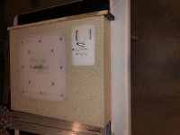
Re your post #1309 pics, what is your technic to get a perfect match for the mounting screws through the plinth into the chassis? Do you make a really accurate pattern? Not much room for error to get the match. Even more difficult with the R.
Thanks,
Don
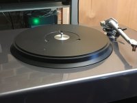
If you're going to the trouble of making a new plinth why not make it Kaneta style and remove the motor from the chassis. The improvement puts the SP10mk2 into another league and it's not a lot more effort.
I strongly endorse this opinion. Together with warrjon, I have been undertaking a relentless improvement to the mechanical aspects of the mk2 industrial design. Ditching the OEM aluminium chassis, removing the electronics to a remote custom enclosure, installing the motor separately in a custom bento/resin plinth, replacing the Technics platter with a custom platter, has contributed to making it the best sounding turntable I have personally experienced, not withstanding the fact that I have owned an SP10R for the past 3 years. (see posts #1488, #1702). The latest iteration has installed a POM/gunmetal platter superbly produced by warrjon. The platter is a 40 mm thick POM layer, with a gunmetal base for stability, additional damping and moment of inertia. Words don't suffice to describe the improvement (otherwise we wouldn't need music!), but the comments I made in post #1702, are even more valid. The addition of a decoupled centre spindle has clearly audible benefits to noise floor and transparency. Warrjon has also implemented a bearing brace to improve the coupling to the plinth, but it is not yet fitted to my plinth. Bravo!If you're going to the trouble of making a new plinth why not make it Kaneta style and remove the motor from the chassis. The improvement puts the SP10mk2 into another league and it's not a lot more effort.
Attachments
the real reason
warrjon and Bon,
The real reason is, I thought I would be in over my head.
Background, I was lucky enough to acquire two really nice SP-10 MK2's. One lightly used near mint the other a backup TT virtually never used - mint. Objective number one was to not screw them up. True HiFi turntables are new to me. Virtually everything about them I have learned from this thread. Thank you both for your large contributions.
I am familiar with the Kaneta style project but never thought about the chassis only. I felt I was in over my head with the electronics separation.
I have precision glass experience from racing sailboats (although not exactly the same) so I felt I could do the plinth. Lot's of details to get right. Thank you again.
Casting number one is this weekend. I'll shoot a few pics.
I was not sure how to navigate the Kaneta or partial Kaneta steps. I do have a remote start/stop sw if that helps.
I do like to try to do the best that can be done so this is likely not my last casting.😀 Definitely wanted to do the turntable upgrade and improve my AT33PTGII cartridge. TT has the EPA100 tonearm.
Appreciate the comments.
Don
Here is a perspective.
Bon's mk2 is out performing his 10R and Michael Fremer's review of the SL1000R was up there with his $200k Comtinuum.
For the Kaneta I left the chassis intact not even in a different case, you can make an insert from MDF et al to fill the platter void.
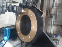
Remove the motor this requires removing the brake which is easy. A 12 core instrument cable and a plug and socket. Remove the connector from the motor, I soldered the lead directly to the motor, Bon used a connector. Solder the motor connector to a short lead to go in the SP10 chassis and drill a hole for the plug.
Mine sports an EPA100 and Stanton 881s and it is one of the best TT's I have heard and I have had the good fortune to listen a few high end rigs including a Continuum.
Bon's mk2 is out performing his 10R and Michael Fremer's review of the SL1000R was up there with his $200k Comtinuum.
For the Kaneta I left the chassis intact not even in a different case, you can make an insert from MDF et al to fill the platter void.
Remove the motor this requires removing the brake which is easy. A 12 core instrument cable and a plug and socket. Remove the connector from the motor, I soldered the lead directly to the motor, Bon used a connector. Solder the motor connector to a short lead to go in the SP10 chassis and drill a hole for the plug.
Mine sports an EPA100 and Stanton 881s and it is one of the best TT's I have heard and I have had the good fortune to listen a few high end rigs including a Continuum.
warrjon,
Thank you for this. I want to make it clear that I was not opposed to the concept but that I lacked expertise to do it. This helps a lot. A couple of quick questions,
1. The brake remains off permanently?
2. The start/stop remains with the chassis?
3. What happens with the timing light?
4. Speed control is maintained independent of the chassis timing light?
Thanks,
Don
Hi Don
1. The brake remains off permanently? Yes all of my SP10mk2's have had the brake removed
2. The start/stop remains with the chassis? Yes, the mk2 has a 3.5mm jack where the power lead is that you can plug a remote start/stop switch into
3. What happens with the timing light? It provides ambiance
4. Speed control is maintained independent of the chassis timing light? Yes, this is just a strobe and speed is locked in the mk2 so as long as the TT is working the strobe is not needed. the 10R has no strobe
casting
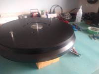
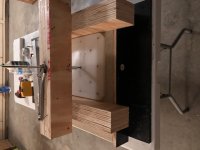
I did my plinth casting this weekend. All went well. Attached some pics. Some highlights, cast upside down, top of plinth/bottom of mold.
I made an aluminum mould bottom to dissipate heat. Worked well as quite a bit of heat is generated.
Total weight of casting material 24.5kg or 54lb,
cast 2/3 resin/bento by weight, 1% catalyst,
I broke it down into two back to back wet pours because of the difficulty in properly mixing everything. It is a very "stiff" and weighty mix. I actually missed it and had to do a partial third mix.
The board across the top with the bolt sticking up is the arm nut cavity. I wanted 100% resin/ bento for the tonearm mount 25mm thick as in Technics arm board. I set up the cavity mould to be mounted after the first pour to squish out material so no voids. Two screws.
One of the pics shows my mixing math with the scale. Kind of fun.
My plan is to let it sit for 5 days and then remove the cavity board and sides and then let it sit for 14 more days on it's face before I extract the displacement forms. They are HDPE.
Please weigh in with thoughts and comments. Especially the timing of the mould and displacement form removal.
Special thanks to Bon and warrjon who have done all the developmental work on this process. Could not have been done without them.
Don
Looks good Don.
Be careful leaving the insert in, as the plinth shrinks there is a possibility of it cracking, I saw this happen to someone else on L/H I think.
Having the TA mounted directly to the plinth is a good idea and both Bon and my plinths are built like this.
This mix has a tendency to warp and will need a fair bit of sanding/filing and filling with polyester auto body filler. Make sure the TA mounting surface is parallel to the platter/plinth top. If it's not, as the arm traverses the LP azimuth will vary.
warrjon,
Thank you. Reflective of all I have learned here.
When do you think the best time to pull them is? Any danger of cracking the plinth on the pulls? They will clearly be pulled using Bon's method, that is using a threaded rod extension against the plinth itself. The two small ones don't have much moment arm on the pull but the big one certainly does. Just want to be smart about it. The forms are tapered @ 2deg. I hope it works.
R,
Don
post scrip
Maybe I can figure out some rig to router mill the TA mount surface parallel. That is not a hand sand thing. I took great care to hold the form to the mould but if the thing warps that is a different story.
Don
Maybe I can figure out some rig to router mill the TA mount surface parallel. That is not a hand sand thing. I took great care to hold the form to the mould but if the thing warps that is a different story.
Don
I found the plinth had warped before it was removed from the mold.
You could use a planer jig for the router.
You could use a planer jig for the router.
Hi Don
Nice Information and Tips to be used on your Plinth Build.
Looking forward to seeing the finished product.
Nice Information and Tips to be used on your Plinth Build.
Looking forward to seeing the finished product.
Thanks.
One other pice of information involves whether you care to have the bentonite to the very top of the casting (bottom of the plinth). The bento will sink and there can be a clear layer of resin 3 to 5mm thick at the surface. One way to avoid this is to only build your mould as deep as the casting you want - not any deeper. Then you can keep adding mix late in the pour letting the bento sink and the resin over flowing the mould. With a little work you can get the bento pretty much all the way to the surface. That's if you care about it.
Whatever floats your boat.
Don
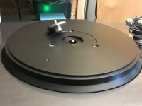
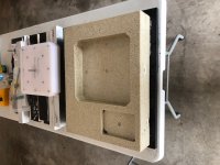
Pulling the inserts
Attached are a couple of pics of the plinth insert pulls. I was shocked how ease they came out. HDPE (cutting boards) and mould release. Everything was basically a copy of Bon's methods. Thank you Bon.
Now for the hard part. Finishing it and setting it up to receive the TT and TA.
First step is to mill the bottom flat then the top to make sure it is perfectly flat and also the tone arm mount surface to make sure it is parallel to the TT surface.
Question, does anybody have any comments about cleaning the mould release off the mould. I worry about adhesion to it with the primers and fillers. There are numerous little cavities irregular in shape and depth. I am guess it is related to the bento and air getting trapped.
I wiped the surface with acetone and then gave the plinth a health washing with simple green.
Nevertheless I worry about adhesion.
Thanks again for all the great advice on this site.
R,
Don
Attachments
Thank you. High praise indeed from the guru of all things design wise. You elevate my game. Besides, the SP-10's deserve a really good home.😀
Don
Don
You are welcome. It is gratifying to see that the instructions were clear and worked well for you.Attached are a couple of pics of the plinth insert pulls. I was shocked how ease they came out. HDPE (cutting boards) and mould release. Everything was basically a copy of Bon's methods. Thank you Bon.
Yes this part will try your patience. I would let the plinth "rest" for a while, then check the trueness again. Pulling the inserts out may cause uneven internal stresses to move it. It is not predictable. Some pours move, others stay rock solid.Now for the hard part. Finishing it and setting it up to receive the TT and TA.
Question, does anybody have any comments about cleaning the mould release off the mould. I worry about adhesion to it with the primers and fillers.
Acetone should be adequate for clean up.
It looks like you plan to use an armboard. I decided that the plinth works best in its role as a vibration sink if the tonearm is directly bolted to the plinth. Admittedly this is restrictive and discourages use of different tonearms. I use epoxy embedded nutserts from below to receive the tonearm bolts. If you do use an armboard, I have used 6-10 mm acrylic with no noticeable quality loss.
Last edited:
- Home
- Source & Line
- Analogue Source
- The Incredible Technics SP-10 Thread