sorry but.....what is "sheer"?
Sorry it's Aussie slang. It means I was lucky to find it with no skill involved.
The little voids and exposed bentonite is by far the hardest part of the finish detail.
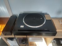
I put the TT into the plinth yesterday for the first time. It fits. Good sign. Wont know about the TA untilI I get the TT mounted. Yes on the stainless.
This whole process is a little scary because it only takes one mistake to possibly cause a redo.
My next critical task is to drill the mounting holes for the TT. Not much room for error there. Got my clear acrylic for the pattern.
Do you drill one size all the way through and have the bolt head and washer on the bottom of plinth or do you counter sink it part way through. Affects bolt length. My Technics Obsidian plinth is countersunk. The plinth is now really close to 90mm thick.
Don
For the mat layup, cut the mat first and check it for fit, then paint the plinth in resin and let it tack off, once it's tacky the mat will stick, then roll the mat flat before wetting out with resin and rolling again. I add black tint to my resin. It will still need a small amount of sand and fill to get it smooth.
I drill the TT mounting holes all the way through, I also us a 6mm drill to give me some wiggle room and washers under the bolts. Drill slowly (300rpm) with a sharp bit. If you spin the bit too fast it will dull very quickly.
Arm mounting boards and other appendages I drill and glue inserts into the plinth. I use West System epoxy for the glue, JB Weld would also be good.
SP - 10
Bon,
Looking back through the Kaneta plinth posts, it looks to me like you left the SP - 10R chassis on when you mounted it to the plinth. Correct me if I am wrong. I know there is a reason but I don't know what your thinking is. Please explain so I can learn. I don't really know how the 10R is built.
Thanks,
Don
Any progress on the bearing @warrjon?
I bought some Vesconite and made inserts which I reamed with a 0.281" reamer this worked ok but I was not happy with the fit tolerance, it was as good as the stock bush but if I'm going to do this I want a better tolerance than stock.
The better way is to bore the bushes (this also gives a smoother finish) which requires the motor to be turned around to bore each end, but holding the motor in the 4 jaw is an issue as the motor housing has draft on the sides of the casting and my 10" 4 jaw does not have quite enough jaw depth to hold the mounting flange to bore the top bush, so I have a a couple microns offset in the top and bottom bushes.
I have devised a way to do this which requires a fixture to hold the motor in the 4 jaw, I made one from 20mm thick aluminium but it warped too much as it was clamped in the chuck, so next is to make it from at least 20mm thick steel.
Bon,
Looking back through the Kaneta plinth posts, it looks to me like you left the SP - 10R chassis on when you mounted it to the plinth. Correct me if I am wrong. I know there is a reason but I don't know what your thinking is. Please explain so I can learn. I don't really know how the 10R is built.
Thanks,
Don
Correct his 10R is stock, it's only the mk2 that is in the Kaneta plinth.
I was doing some testing of my servo linear arm with a stethoscope and decided to put the stethoscope on the SP10mk2 OEM platter. One of my spare SP10's is stock in a resin/bentonite plinth.
Putting the stethoscope on the platter mat and tapping the platter, chassis and plinth ringing was clearly audible.
Doing the same tap test on my SP10 in the Kaneta with POM platter it was totally inert just a very dull thud no matter where I tapped. This is why the POM platter and remote motor mounting makes such a huge improvement.
Here is a good example of the amount of energy the stylus imparts on the LP which in turn goes into the bearing and platter and the need to damp/control this vibration. At the end of the page there a recording with a contact mic on the bearing housing.
Turntable Main Bearing Vibration, Part III
Attachments
Bon,
Looking back through the Kaneta plinth posts, it looks to me like you left the SP - 10R chassis on when you mounted it to the plinth. .... I know there is a reason but I don't know what your thinking is. Please explain so I can learn. I don't really know how the 10R is built.
Thanks,
Don
Hi Don.
The reason is simply concern for my substantial investment. The thought of de-constructing a mint, near new 10R, is just a teeny bit daunting.
I had a few mk2 in average/poor cosmetic condition, so choosing one for the Kaneta project was an easier decision.
Based on my considerable time with the Kaneta mk2, I am confident doing the same with the 10R would blow my mind. The reason Marc Gomez of SAT selected the 10R as the basis for his turntable, are well documented.
Don't get me wrong, the 10R is a great turntable, but mine is covered up next to the Kaneta mk2. With the Kaneta mk2, every LP reveals details that I never knew were there, even on the 10R. I have paused testing because listening has become so interesting. It has got to be connected to lowered noise floor, resonance control.
I bought some Vesconite and made inserts which I reamed with a 0.281" reamer this worked ok but I was not happy with the fit tolerance, it was as good as the stock bush but if I'm going to do this I want a better tolerance than stock.
The better way is to bore the bushes (this also gives a smoother finish) which requires the motor to be turned around to bore each end, but holding the motor in the 4 jaw is an issue as the motor housing has draft on the sides of the casting and my 10" 4 jaw does not have quite enough jaw depth to hold the mounting flange to bore the top bush, so I have a a couple microns offset in the top and bottom bushes.
I have devised a way to do this which requires a fixture to hold the motor in the 4 jaw, I made one from 20mm thick aluminium but it warped too much as it was clamped in the chuck, so next is to make it from at least 20mm thick steel.
warrjon,
I think I lost track somewhere. Why don't you just make a bushing.
Don
I bought some Vesconite and made inserts which I reamed with a 0.281" reamer this worked ok but I was not happy with the fit tolerance, it was as good as the stock bush but if I'm going to do this I want a better tolerance than stock.
The better way is to bore the bushes (this also gives a smoother finish) which requires the motor to be turned around to bore each end, but holding the motor in the 4 jaw is an issue as the motor housing has draft on the sides of the casting and my 10" 4 jaw does not have quite enough jaw depth to hold the mounting flange to bore the top bush, so I have a a couple microns offset in the top and bottom bushes.
I have devised a way to do this which requires a fixture to hold the motor in the 4 jaw, I made one from 20mm thick aluminium but it warped too much as it was clamped in the chuck, so next is to make it from at least 20mm thick steel.
Any additional lubricant or just using the self-lubricating properties of the Vesconite? If the latter what's the ideal shaft clearance?
I'd be interested to learn more about your fixture. I've a TTS-8000 that I need to refresh the bearings on so I can send it on its way. I've a baby lathe which makes things quite a bit more challenging, and not a lot of experience.
Co
Here is a good example of the amount of energy the stylus imparts on the LP which in turn goes into the bearing and platter and the need to damp/control this vibration. At the end of the page there a recording with a contact mic on the bearing housing.
Turntable Main Bearing Vibration, Part III
As this was consequential to what they were testing, did they ever make a focused effort? Off the bat I wonder the sensitivity of the pickup, gain of the mic pre, and the gain they said they applied after the fact.
warrjon,
I think I lost track somewhere. Why don't you just make a bushing.
Don
I did try a brass sleeve with pressed in the Vesconite but tolerance for press fit of the brass was an issue.
I have replaced the balls in a few SP10's now and tapping the ball out every one has driven the bronze sleeve out first. Sleeve bearing need to be a press fit. What were Technics thinking. The interference slip fit is just not good enough. I suspect this is one factor why my crude PTFE bush had less patter vertical runout then the OEM bush.
When a busing is press fit it also reduces the ID of the sleeve for the shaft so to get a very close tolerance fit for the shaft the ID needs to be bored.
I have replaced the balls in a few SP10's now and tapping the ball out every one has driven the bronze sleeve out first. Sleeve bearing need to be a press fit. What were Technics thinking. The interference slip fit is just not good enough. I suspect this is one factor why my crude PTFE bush had less patter vertical runout then the OEM bush.
Interesting I've only had that happen once of a few dozen motors.
Vesconite needs no lubricant. It has 10 time lower coefficient of friction Vecsonite to steel dry than lubricated sintered bronze. It was specifically formulated as a sleeve bearing polymer to run in harsh conditions.
You would think 20mm thick aluminium would be pretty strong, but I measure 0.05mm warping of the motor housing bolted to the 20mm ally, no good if I want to hold 0.005mm tolerance
The fixture will be about 220mm OD to prevent it warping when clamped. It will be bored for the motor and bolts added to stand the motor off the fixture. The bolt center will be drilled and tapped M4 which is what the motor will bolt to. I then take a skim cut off the bolt heads to true it up so the motor does not wobble around its center.
This MUST be done in a 4 jaw chuck so the motor spindle housing can be dialed in with an indicator inside the housing.
Hi micgum1967
Welcome to the Thread, there has been quite a few contributions recently that can be quite infectious.
IMV any of your experiences are welcome to be shared.
I am being guided by a friend, and we are in the early stages of arranging for the recreation in the UK of some of the projects carried out by warrjon.
- Home
- Source & Line
- Analogue Source
- The Incredible Technics SP-10 Thread