I have deconstructed a selection of Vintage Japanese DD TT's back to the bearing Housing, and some have had the Platter Spindle Removed with the Bearing Housing Inner inspected.
These are visual inspections only, finding a evidence of a lubrication that could be referred to as present, is not a discovery I have had to date.
The SP10 MkII I own has been supplied fully overhauled, so I am not with a curiosity about the Bearing on this model.
A Modified Bearing using modern materials will always get my attention, especially if the Tolerances for the parts used, show other measurements that are recorded are improved for the better.
Such a addition will outlast my years left to listen with a reasonable hearing quality.
I've had a look at the TTS8000 bearing and it's different to the SP10mk2, the TTS is a better design. The SP10mk2 bearing is a single bronze bush with 9/32 bore all the way through which is worst way to implement a journal bearing. The TTS bearing being 2 bronze bushes separated by a spacer with a larger ID is what I'm looking to achieve with a new SP10 bearing.
Debatable if the design is better for the given application but in the three examples I have had through here the implementation led to a far poorer end result.
1st year engineering students know a hydrodynamic bearing shaft should only be held at each end for best performance. No shaft is absolutely straight and no hole perfectly uniform in ID, holding a hydrodynamic bearing along its entire length increase precission and hydraulic hammering.
Secondly the bearing sleeve in one of my SP10's is badly scored so it must be replaced. If machined to Class III tolerance with better materials that are available these days (like Vesconite) why would the bearing be worse? Poor outcomes are the result poor implementation.
Secondly the bearing sleeve in one of my SP10's is badly scored so it must be replaced. If machined to Class III tolerance with better materials that are available these days (like Vesconite) why would the bearing be worse? Poor outcomes are the result poor implementation.
Bummer with all that they got right on these 'tables that they got something so basic so wrong, and continue to do so on their new models. How much hydraulic hammering do you reckon happens at 33 RPM?
As far as your bearing, I never mentioned it - I was talking about the topic at hand, which was the TTS-8000, and I specifically said the implementation led to a poor result.
As far as your bearing, I never mentioned it - I was talking about the topic at hand, which was the TTS-8000, and I specifically said the implementation led to a poor result.
I think that the bean counters probably overruled engineering with regards to the bearing. The bearing in the SP10 is cheap to manufacture as it can be machined outside of the motor then inserted.
The other issue with the mk2 is the C clip under the rotor that decreases spindle OD and is a flex point. Another thing to upgrade at a later date.
The issue is, without the right test equipment it's difficult to measure noise differences in bearings with any certainty, ie the measurement uncertainty can dwarf the actual measured value.
Any oil filled journal bearing will hydraulic hammer, and this is made worse with a bearing like the SP10 that is full length. Exactly how much this will effect SQ is unkown. I don't think a better bearing would be audible in a stock SP10mk2 due to other coloration due to the chassis.
My solution is to run a dry bearing with the sleeves made from a self lubricating thermopolymer. Linn have used thermoplastic for the LP12 bearing since its inception and these are well known to very quiet.
I figure I have nothing to lose as the bearing is damaged anyway, which I didn't notice when I rebuilt the motor as the damage is about 5mm below the top of the sleeve so it's not visible. I found it a week or so ago when I removed the rotor to check thrust pad wear and slid a bore gauge down the sleeve to check the sleeve was in tolerance.
Last edited:
You'll find that all the sleeves have scoring - appears to be a byproduct of how they were made. Also doesn't seem to adversely affect performance. The MK3 is a solid journal as well and nothing about that design or implementation says cheap. We'll never know what the actual trade-offs were, sadly.
I've never managed to measure "coloration" due to the chassis. In the same vein I find the rigid approach to be a crapshoot as it doesn't take in to account the dynamic system. A specific implementation may be good or it may be bad but I haven't seen any with actual engineering behind them. Only theoretical application of broad principals, typically (misapplied) static.
Yes, we have great materials at our disposal today. I have couple TTS-8000s here I'd love to get rid of, but won't let them out the door with the existing bearing performance. Synthetic was on my list for those.
I am not experienced but may be engineers thought of having fine balance between durability and bearing noise to have a single through bearing on SP10 instead of two bushes ? Probably will have less eccentricity as well in long run as these were made to run long period of time ?
in other words I am thinking on lines that even if single through bearing will have wear, the lost tolerance will be compensated by non worn areas because we now have comparatively large surface area ?
regards
in other words I am thinking on lines that even if single through bearing will have wear, the lost tolerance will be compensated by non worn areas because we now have comparatively large surface area ?
regards
This sleeve is so badly scored it's effecting TT performance.
If you're trying to measure TT performance with FFT the digitization process will effect the measurement. The issue with most FFT analyzers is the sweep time increases as FFT length increases and it's very easy to miss spurious transients. When measuring transient response in the calibration lab we only used swept tuned analyzers for this reason.
The TT system has to be symbiotic and all components need to work in harmony. Rigidity needs to be used in conjunction with damping or as you know you end up with a resonant system. With my builds I researched what the high $$ well respected TT manufacturers were doing and combined this with Physics and the results have been exceptional.
I just measured vertical runout of a platter on my old black SP10 that is still in its chassis and another motor I have put a PTFE sleeve into. Measurement was done with a Mitutoyo test indicator at the edge of the platter. OEM was motor driven and PTFE was hand spun as there are no guts in the motor ATM. This was just a proof of concept. The PTFE bearing was hand reamed and a little over size at the top. I now have a 0.2812" machine reamer to ream in situ on the lathe.
Total indicated runout OEM 0.14mm new PTFE bearing 0.06mm. This looks promising so I'll redo the bearing put the motor back together and test it in the chassis under power.
How is the effect manifesting?
Many different ways to measure things, and clear goals and objectives always help. Recognizing that I don't have the equipment, environment, specific skills, or experience in directly measuring such small amounts of energy in any meaningful way, and that I lack the motivation to overcome that, I investigate viable proxies.
Any modifications I make to a 'table are with the objective of improving performance, which means more accurate sound reproduction. With that in mind we can cut to the chase and measure/test the end result, if only for differences. This is mind-numbingly tedious work as vinyl reproduction is so inconsistent you can't just measure A once and B once and draw a conclusion (not that one should do that, ever), rather you need to measure each 20+ times, different times of day, atmospheric consistency, etc. After all that the most prominent thing you're likely to find in absence of gross influences is environmental because heroic measures to isolate the DUT weren't taken.
In my early days I had a lot of self-proclaimed successes though with further scrutiny and rigor a lot of them were far less meaningful or downright meaningless. A fair number of gems held-up, thankfully. It was well worthwhile as I learned what to focus on and my time is much better spent these days. Regardless of outcome everything is a learning opportunity to be benefited from.
I appreciate your stance on your approach and that you're happy with the results, but I'm sure it's no surprise that I find it overtly broad and no different than what I said I find problematic in the first place.
I look forward to seeing more on your bearing. Are good before and after measurements to accompany this exercise? I'm always after data.
The effect is physical not measured the TT shakes, it's taken me months to find the problem because it's intermittent (happens maybe once ever 10-20 LP's) and I was looking for an electronic fault. I found the sleeve damage by sheer dumb luck.
I'll agree it's very difficult to measure what I'm hearing with regard to the improvement with my SP10. I know from a lot of years experience repairing and performance testing electronic equipment the need for rigor in test environment. After repairing a HP 3458a it was left in a temperature and humidity controlled lab to thermally stabilize for 24hrs before performance testing. One of the hardest bits of test gear I have had the fortune to test was a Keithley 410a Pico Amp Meter without a proper test methodology noise swamped the signal.
I will measure the new bearing for my own information. As I'm replacing a bad bearing sleeve I'm more interested in reducing platter runout and vertical pulsing as the spindle precesses.
How many TT manufactures publish test results, the reason for this is the difficulty in measuring TT performance even with suitable test equipment, which few to no DIY's will have access to. There was a time when HFN tested TT's and published the results but this is now few and far between.
I posted these mods so anyone interested in modifying an SP10 has a starting point. The SP10mk2 is a good deck stock and out performed both my Rega RP8 and LP12, modifying it to damp/control vibration energy has improved it significantly. The methodology I have used throughout this journey is to review what the top TT manufacturers have done and adhere to the know laws of classical physics.
Sure, I get it, I just don’t ascribe to the broad rationalizations. Not to say that I wouldn’t love for some of this to bear fruit, but in the absence of any evidence it’s just another anecdote on an audio forum.
It can be done
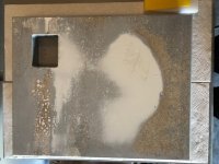
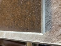
Attached are 2 pics of my plinth project. I wanted to take some time at this point to explain my process because it may help future builders.
To start with I had a very flat top of plinth (bottom of mold) and sides very square to it. The open top of the mould (bottom of plinth) naturally was rougher and not quite parallel to the top. Slightly uneven and with a slight slope 2-3 mm. I wanted to see if I could get it absolutely parallel to the top of the plinth.
I do not have a CNC so I built a planar sled using 4in wide by 1/4in thick aluminum channel that rested in the table surface the plinth was resting on. I then built a sled that I could slide along the rails and push my router across. I had an undersized 1/4in Makita battery powered router and a 1in surfacing bit.
I used water to cool the bit knowing it would do something with the exposed bentonite. Didn't know what. It took 25 or 30 passes per cut. I took 3 - 1mm cuts.
It was messy but it worked perfectly. The plinth is now absolutely square and the top and bottom absolutely parallel. The plinth is shown here after one coat of primer and some glazing putty primarily to help fill little holes left by the washed out bentonite and a low spot shown by the large white area that I chose not to try and mill out. It was 1-2 mills low but the edges are perfect. I miked the edge thickness in 12 locations around the block and they all came out within 1/2mm.
I was amazed and very happy.
I then wanted to see if I could put a 1/4in chamfer on the corner and that also looks like it will work. I am goin to try and put a 1/2in chamfer on the top. I know this is the hard way to do corners with resin/bentonite but I wanted to see if it can be done and it looks way cool. I think it will work.
I am board sanding everything to maintain flat and square surfaces and straight chamfer edges.
The point of all this is I think it is possible to have a great looking resin/bentonite plinth with modest equipment if you choose to go that route. After all, this is DIY.
Again, thanks to Bon and warrjon who have done most of the heavy lifting with this material.
Regards,
Don
Attachments
Looks great Don,
The router planer jig is a great way to flatten the plinth. I ended up covering my whole plinth in 1 sheet of glass mat and resin to get a smooth surface.
The router planer jig is a great way to flatten the plinth. I ended up covering my whole plinth in 1 sheet of glass mat and resin to get a smooth surface.
I wanted to take some time at this point to explain my process because it may help future builders.
Don
Hi Don.
It looks good so far. One reason I went for rounded edges is for comfort of lifting. You will end up with a turntable weighing around 40 kg, which can be hard on the hands.
Also since you are getting closer to painting, I may have mentioned previously, seal the inner voids carefully and use stainless steel bolts and hardware.
I found the sleeve damage by sheer dumb luck.
sorry but.....what is "sheer"?
The little voids and exposed bentonite is by far the hardest part of the finish detail.
I put the TT into the plinth yesterday for the first time. It fits. Good sign. Wont know about the TA untilI I get the TT mounted. Yes on the stainless.
This whole process is a little scary because it only takes one mistake to possibly cause a redo.
My next critical task is to drill the mounting holes for the TT. Not much room for error there. Got my clear acrylic for the pattern.
Do you drill one size all the way through and have the bolt head and washer on the bottom of plinth or do you counter sink it part way through. Affects bolt length. My Technics Obsidian plinth is countersunk. The plinth is now really close to 90mm thick.
Don
warrjon, just curious. Did you vacuum bag the mat? I haven't had good success with just hand layup in terms of finish detail. Prepreg?
Don
Don
If you don't want to counterbore threaded rod and shouldered barrel nuts would work and minimize protrusions on the bottom.
The little voids and exposed bentonite is by far the hardest part of the finish detail.
I put the TT into the plinth yesterday for the first time. It fits. Good sign. Wont know about the TA untilI I get the TT mounted. Yes on the stainless.
This whole process is a little scary because it only takes one mistake to possibly cause a redo.
My next critical task is to drill the mounting holes for the TT. Not much room for error there. Got my clear acrylic for the pattern.
Do you drill one size all the way through and have the bolt head and washer on the bottom of plinth or do you counter sink it part way through. Affects bolt length. My Technics Obsidian plinth is countersunk. The plinth is now really close to 90mm thick.
Don
Don,
When I made mine Plinth, I used a 1" Forstner bit to counter sink the bolts, then drilled the holes. So no heads protrude from the bottom.
Rush
- Home
- Source & Line
- Analogue Source
- The Incredible Technics SP-10 Thread