Hi Carlo,
The acrylic I used for my platter did vary across its width. This did result in the platter being a bit thicker on one side to the other. I can't remember by how much, probably in the region of 0.2mm. Although it varies in thickness the surfaces are quite flat. The billet I made the platter from was slightly wedge shaped. It would have been nice to have a lathe to allow me to make the platter with uniform thickness. Whilst making the platter everything was constantly referenced to the upper surface. The platter has balancing weights in the sub-platter. Together these measures overcome the problem of the non-uniform thickness.
I'm also a fan of full range drivers, be they panels or cones. I've just taken delivery this week of a pair of Jordan Eikona 2 drivers. I'm very excited to get out my new circular saw and start making sawdust.
Niffy
0,2 mm difference is reassuring, with the dial indicator+blue-ink+scraping method could be flattened.
I'm planning to machine the sub-platter - my lathe goes up to 150mm ca - to get the bearing perfectly aligned. So the balance on the sub-platter is a good solution, for aesthetics too.
carlo
speakers: I've built the Fostex 208 sigma BHL enclosures: really big and heavy and quite complicate, but a pleasure to hear once correctly damped (for a chamber music addicted).
Hi Walter,
You could use a massive reflex clamp to flatten records. Because of the way the reflex clamp works it does require a considerable amount of force, probably more than that required for a peripheral clamp. I estimate that I use between 20 and 30N of force with my clamp. This would need a clamp of 2 to 3kg to exert the same force by weight alone. You will be adding this much load to the turntable main bearing. If you have a 55lb platter and a matching bearing this will probably not be a problem. If you have a more modestly weighted platter then you could easily be overloading your bearing. Also all of the additional mass is located near the centre of rotation so will add little to the rotational inertia. My screw down clamp by comparison weights just under 100g. If you do not have a threaded spindle it can be difficult and daunting to add a thread. Often the spindle is made of a hardened material that would be very difficult to cut a thread into. The SME clamp I used to own used a collet that gripped the spindle then pulled upwards so it is possible to have a screw down clamp without having a threaded spindle.
Niffy
Hi Coolerooney,
I'll try to answer this using a slightly different example to the one you suggested.
If I have a 20um/mN cartridge in an arm with effective mass of 12.67g I will get a resonance of 10hz. If playing a record with a 0.5mm eccentricity (1mm visible wobble) the cantilever will be deflected, due to the inertia of the arm, by a maximum of 1.4um. With a 6mm cantilever (Carol's cart) this equates to a tracking error of 0.013°
If I quadruple the mass of the arm to 50.7g the resonance frequency will be 5hz. The maximum deflection will now be 6um which equates to a tracking error of 0.057°, still to little to be overly concerned with.
However the movement of the cartridge body above resonance, in the audio band, is reduced by 12dB with the heavier arm. This makes a significant difference especially at very low frequencies.
The equation I used to determine these figures is a bit of a mouthful and takes the damping of the cartridge and the resonant frequency of the system into account . For determining the deflection due to eccentricity a much simpler equation can be used.
d=emcw^2
Where d is stylus deflection (um)
e is eccentricity (mm) (half the amount the cartridge moves)
m is the effective mass (kg)
c is compliance (um/mN)
w is angular velocity (rad/s) (3.49 at 33.3rpm)
For the example of the 20um/mN cart on 12.67g arm deflection would be 1.54um. Reasonable similar to more accurate equation, the difference is due to the more simple equation not taking damping into account.
Niffy
Niffy & nocdplz,
Revisiting this topic from page 261 and onwards——-
I am trying to reconcile the calculations of you and the pics of nocdplz, at 10mN deflection— one give micrometer displacements, other serveral tenths of mm’s
I am still mystified-
If a cartridge is 20mum/mN, it describes the movement relative to force- which force is this, where does it come from and how much is it?
My assumption-wrong off course- is an arm has an effective mass of 20 grams, this equals a force of 200mN, compliance =20, then the stylus would move 200x20mum=4000mum=4 mm ???
Trying to get picture of the stylus movement in normal operation, not eccentricity
How far does the stylus/cantilever go out whack when its slugging 20 grams around
")
What am I missing here, how can it be reconciled
Thx
Best
Coolerooney
Attachments
Last edited:
Like to add this article by SE Grimm
He indicates a movement of 2,5/3 microns -after the bearing, indicating that this is 10% of the stylus movement
Vinyl Turntable Equipment: DIY phono cartridge
The flexibility of the elstomer bearing seems logical, otherwise the whole arm would resonate- is it then correct to say that the arm follows the stylus with 25 micron increments?
Hi Coolerooney
what a mess: sorry I can't say more than what I've already said, Niffy will certainly be more scientific.
Consider that:
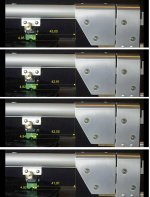
the first image is the analysis of the video of my "crash test" (1.3 mm eccentricity and 3 mm warp are limit conditions, never seen on listenable disks) and the measurements are related to the dynamic bending caused by those defects (accelerations). Since no one publishes videos of this kind, and everyone loves to see just what confirms his opinions I explained that for me "the severe side bending" was more similar to that of a damped pivoted than a linear one, thanks to a horizontal mass much lighter than normal (no shaft and no relative counterweight) - See post #2547.
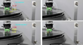
the second image is the measure of static bending (uniform motion) similar to what is caused by frictions and levers of the carriage+shaft.
Niffy calculates this stylus bending using the compliance: his method is absolutely correct and brilliant, but the results differed from what I observed (not too much, 2 or 3 times bigger, a possible mistake with homemade tests). Hence my doubt about the compliance measure provided by the manufacturers: compliance is usually used to calculate the resonance of the system, so my hypothesis was that it is measured for micro movements of the stylus during tracking and not for the bigger forces that may generate a bending. See post #2621
Now: the effective mass (vertical and / or horizontal) is an inertia, so it comes into play only when there is an acceleration: horizontal for eccentricities, vertical for warps . Not during the uniform tracing motion. Many valid passive realizations - mechanical, or on air bearing - commercial or Diyed - use carriages with relevant weight (> 50 gr), with reference results.
If this is your problem, maybe you are off track: the problem is the carriage friction, not the weight.
But even this does not concern you, since you will use an active system, and sophisticated gadgets to cancel warps and eccentricities, if I remember well. You're going to face many others that i can barely imagine
carlo
I knew that article. I can't wait he will be able to build such a cartridge, an essential complement to dream tonearms; but I'm afraid I'll die long before I can see it, happily listening to good music with a simple unipivot and a nice Dl103, coming from 50 years ago tech.
what a mess: sorry I can't say more than what I've already said, Niffy will certainly be more scientific.
Consider that:
the first image is the analysis of the video of my "crash test" (1.3 mm eccentricity and 3 mm warp are limit conditions, never seen on listenable disks) and the measurements are related to the dynamic bending caused by those defects (accelerations). Since no one publishes videos of this kind, and everyone loves to see just what confirms his opinions I explained that for me "the severe side bending" was more similar to that of a damped pivoted than a linear one, thanks to a horizontal mass much lighter than normal (no shaft and no relative counterweight) - See post #2547.
the second image is the measure of static bending (uniform motion) similar to what is caused by frictions and levers of the carriage+shaft.
Niffy calculates this stylus bending using the compliance: his method is absolutely correct and brilliant, but the results differed from what I observed (not too much, 2 or 3 times bigger, a possible mistake with homemade tests). Hence my doubt about the compliance measure provided by the manufacturers: compliance is usually used to calculate the resonance of the system, so my hypothesis was that it is measured for micro movements of the stylus during tracking and not for the bigger forces that may generate a bending. See post #2621
Now: the effective mass (vertical and / or horizontal) is an inertia, so it comes into play only when there is an acceleration: horizontal for eccentricities, vertical for warps . Not during the uniform tracing motion. Many valid passive realizations - mechanical, or on air bearing - commercial or Diyed - use carriages with relevant weight (> 50 gr), with reference results.
If this is your problem, maybe you are off track: the problem is the carriage friction, not the weight.
But even this does not concern you, since you will use an active system, and sophisticated gadgets to cancel warps and eccentricities, if I remember well. You're going to face many others that i can barely imagine
carlo
I knew that article. I can't wait he will be able to build such a cartridge, an essential complement to dream tonearms; but I'm afraid I'll die long before I can see it, happily listening to good music with a simple unipivot and a nice Dl103, coming from 50 years ago tech.
Last edited:
Yes: as said 0.37 mm observed, 0.065 mm calculated with the compliance = 5,6 times more.
Obviously the tip remains steady into the groove, while the arm is pulled by the weight, rotating on the elastomer: where is the problem?
An advice: to do your own calculations according to Niffy, and your own test according to my setup: an hour spent so takes away a lot of doubts, diyer's style.
Now a curiosity: why do you worry about stylus bending? with your active arm absurd weights and excessive frictions of the carriage mean nothing at all (if it works, that's why they make them).
Your bending will vary between the threshold of the servo and 0, and then between the threshold of the servo and 0, and then between the threshold of the servo and 0, and then between ...
ciao carlo
Last edited:
I think that test was the static test with 10mN of force. With your 20um/mN cartridge the calculated deflection would be 200um or 0.2mm. Your measurement of the photos showed 0.37mm which is 1.85 times as great. I think the 0.065mm deflection was on the dynamic test and cannot be directly compared to the 0.37mm deflection. I thought your measurement was a bit pessimistic at the time, I thought your photos showed less deflection.
I have a thought on how to measure the static compliance more directly and it doesn't rely on photographs. It should be much more accurate and simple to perform. It will use my stylus force gauge and micrometer. Unfortunately as I was setting up the force gauge ran out of battery. I've ordered a new battery and if it works out will post results. It will definitely be interesting to see how published manufacturer dynamic compliance figures compare to measured static compliance.
Hi Coolerooney,
If you have the entire 20g under the acceleration of gravity you will indeed have about 200mN of down force which would be disastrous for your cartridge. The arm is counterbalanced so only a couple of grams are supported by the stylus. The effective mass is about how much the arm will accelerate due to a force acting on the stylus and how the compliance of the cartridge will interact. It doesn't represent the force acting on the stylus.
Niffy
But, but......
The arm is balanced within 2 grams of VTF, isn’t the mass that is important, when changing its direction, vertical or lateral? -same as it is required to get the right resonance? F=mxa springs to mind and the effective mass is calculated by taking the F = mxa into account for each main component- right?
According to the earlier quote of Kuzma:
“The effective mass of a tonearm is a figure in grams. It represents the ‘force’ needed on the diamond tip to move the tube at the bearings.”
Probabaly I am mixing things up, but then I am a true Noob ahahahaha
Best,
Coolerooney
Last edited:
Hi Coolerooney,
I originally questioned Frank's statement as it is not well worded making it confusing. I'll forgive Frank as he is a genius and English is not his first language.
His statement is:
“The effective mass of a tonearm is a figure in grams. It represents the ‘force’ needed on the diamond tip to move the tube at the bearings.”
Our good friend Mr Newton says, as you pointed out, that force = mass x acceleration.
From Frank's statement "effective mass" represents "mass" fron Newton's equation.
"'force' needed" represents "force" and
"move the tube at the bearings" represents "acceleration"
"move the tube at the bearings" is ambiguous as it could refer to bearing friction as well as inertia.
The statement does seem to read that the effective mass is a force. It is actually saying that the effective mass needs a force (applied on the stylus) in order to move.
Hope this clears things up.
Niffy
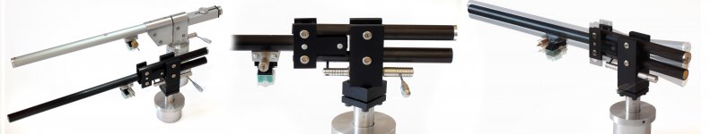
Lil Casey MK2 carbon -- the radial rail tonearm
This new arm (see #2758 - #2833) represents an evolution of the first Lil Casey, to which may refer those interested both for the conception #2355 #2383-4, construction #2440 #2469-70 and measurements. #2547 #2574-2605.
Even if the previous arm behaves correctly (carriage effortlessly sliding) and plays pleasantly my records since a couple of months, there remained two weak points to work on: excessive vertical eff. mass - frictions on the parallelogram.
Since the signal is generated simultaneously by both horizontal and vertical movement of the stylus, imho the vert. and hor. effective mass should be quite similar to get a coherent behavior. I know there are completely different opinions and theories, but this is mine.
In order to improve those aspects I've used a carbon fiber tube to halve the moving masses and pen tip bearings to reduce parallelogram frictions, obtaining a simple compact arm with the same comfort of use of the previous one (rotatable and leveling base, lifter) and -hopefully- better performances on warps.
The arm is just ended, but from the first tests the movements seem OK: the carriage sliding is just a bit worse, while the vertical articulation (the main goal of this design) is greatly improved.
The construction needs just a (small) circular saw and pillar drill, but can not be called trivial - skill, templates and a lot of care are necessary, especially for the geometry of the parallelogram.
Photos and construction drawings as attachment
carlo
Niffy, I am curious to know your method of measurement, certainly less naive than mine: and given that the variations with respect to the calculation were significant but not huge (in the second answer, reading the old post in a hurry I kept the wrong data ) certainly the problem deserves to be better examined
Attachments

Hi Carlo,
As always I am thoroughly impressed with the fit and finish of your work. Lil Casey mk2 looks amazing. Hope the sonics match the visuals.
I have heard many people say that vertical and horizontal effective masses should be the same. It is one of the main criticisms leveled at linear tracking arms, that the vertical and horizontal masses are different. Although I have heard it stated that they should be the same I have never heard a cogent reason for this to be the case. I have solid reasons why it is better for them to be different. Could you please expand on your reasoning for them to be the same.
If you don't mind I'll wait for the new batteries for my stylus force gauge to turn up. Then I can post pictures and a description of the test as well as any results.
Niffy
Hi Niffy,
I am not 100% sure why vertical and lateral masses should be same either. I assume the resistance of the damping rubber which holds cantilever is same in every directions, i.e. 360 degree. So, the difference in vertical and lateral masses may cause difference in output. However, I can be wrong.
Jim
I am not 100% sure why vertical and lateral masses should be same either. I assume the resistance of the damping rubber which holds cantilever is same in every directions, i.e. 360 degree. So, the difference in vertical and lateral masses may cause difference in output. However, I can be wrong.
Jim
In a way the different masses do cause a difference in output. The higher mass will stop the cartridge body from moving as much. The output signal generated by the cartridge body's movement is an unwanted distortion, reducing it is a good thing. This is more down to the compliance being lower relative to the mass. The use of a higher mass will result in the damping ratio being reduced which is to be expected as the same amount of damping is being used on a greater mass. This mainly effects the arm/cartridge at resonance.
Niffy
Niffy
Vertical & horizontal mass
Not much more than what said in those two words. Seems so complex to model that is easier to have opinions than reasons
Here some points
1 - If the stylus was alone in the world we would get a pure signal: everything around it, from the cartridge body, introduces complex resonances that go to compose (sum or difference) the signal itself. Every part of the system influences each other
2 - There are no separate horizontal or vertical movements of the stylus, only complex movements in a cone whose vertex is a point inside the elastomer, shifting with resonance feedbacks
3 - The elastomer is a cylinder of homogeneous material (not a prism with different sides) that reacts with its compliance to the movements of the stylus - the only inhomogeneity is the inclination induced by the VTF, with respect to which the manufacturer positions the generator.
From this the simple conviction that it is not worthwhile to complicate my life by introducing unpredictable inconsistencies: on pivoted ones matching the axes of rotation, aligned with the stylus tip, here trying to get masses similar to those for which are designed the cartridges (there is only one effective mass for the calculation, not two).
Experience tells me that decoupled tonearms, with their mechanical discontinuity, sound very different from each other (better? worse? i don't care at all) and this makes me so suspicious to avoid them as much as i can.
Of course these are only my impressions, meaning nothing more than others: only trying not to confuse the role of the effective mass with the absorption of resonances due to the impedance (and mass of course) of the material.
carlo
Knowing the sophistication and precision of your constructions, your appreciation was greatly appreciated - thx Niffy
Hi Coolerooney,
I
The statement does seem to read that the effective mass is a force. It is actually saying that the effective mass needs a force (applied on the stylus) in order to move.
Hope this clears things up.
Niffy
Hmm, not really.....
Tried to apply the F=mxa to an hypothethical arm- taking a page of your post 2599+some Kuzma sauce
Length 20 cm, weight eff 20 grams- no bearing friction
Gives an F of 0,004 Newton (0,2x0,02) multiplied with a cartridge compliance of 22 mu/mN would give a deflection of the cantilever of 0,088 mm, or 88 microns- this seems a reasonable number- any bearing friction would be additional-potentially pushing it to 0,1-0,2 mm
Food for thought:does a normal pivot arm do a better job than TT’s in keeping the cantilever/stylus at right angles vs the groove, due to the ability to use antiskating??
Best,
Coolerooney
Last edited:
- Home
- Source & Line
- Analogue Source
- DIY linear tonearm