Renron: I think others have covered the brass/aluminium issue better than I can, but the essential for electrolytic corrosion is the electrolyte - in my case sweat. I can only assume that if you put the two parts together without getting sweat on them, there's less of a problem.
You can estimate the effective mass of a pick-up arm using f = 1/2*pi*sqrt(m*c). Where f is the subsonic resonant frequency (found using the test record), m is the effective mass, c is the compliance of the cartridge. Usually, you don't know the compliance of the cartridge, so you have to do two tests, one with an extra mass perhaps (15g) stuck to the headshell (and balanced out), and solve the two equations simultaneously to extract the effective mass of the arm. Frankly, I've never done it. As you've pointed out, a low compliance cartridge needs a high mass arm and vice versa.
As it happens, I have a Denon DL103 and am thinking that what it needs is a brass body (to get the effective mass up). But that would cause problems going onto the aluminium headshell.
EC8010,
I did a bit of research yesterday on galvanic corrosion between dissimilar metals. What I found was very interesting.
Ya' know, you just never know where a project will lead you, and the seemingly unrelated facts you'll learn.
Here is a text and chart of reactionary values of dissimilar metals.
Added moisture aids the galvanic process, ie; sweat, humidity or worse yet acid environments.
Only sure way is to prevent continuity. I'm going to use one of these as a gasket between the tower pieces and the gallows arm.")
Ron
I did a bit of research yesterday on galvanic corrosion between dissimilar metals. What I found was very interesting.
Ya' know, you just never know where a project will lead you, and the seemingly unrelated facts you'll learn.
Here is a text and chart of reactionary values of dissimilar metals.
Added moisture aids the galvanic process, ie; sweat, humidity or worse yet acid environments.
Only sure way is to prevent continuity. I'm going to use one of these as a gasket between the tower pieces and the gallows arm.
Ron
Attachments


Going off on a tangent here, but, Zinc Phosphate, which I use as a conversion coating on aluminum prior to powder coating has a fantastic side benifit. It's dielectric as well as a corrosion prohibitor! I'll try it out and see if it works on polished surfaces of aluminum and brass. Easier to detect any etching if it's polished first. Once again, just thinking out loud.
Ron
Ron
Jeff,
How did you calculate the length of the gallows arm(s)?
Does it matter?
The only thing I can think of where it could be a problem is if it's too short, the counterweight would bump the arm.
Almost finished with my mechanical drawing to give to the machine shop. I still can't believe how detailed and complicated this is.............it looks so simple at first glance.
Ron
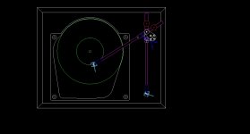
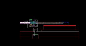
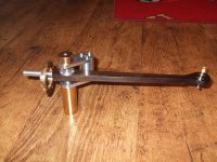
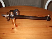
The arm was a co-development with the plinth I was building for my Garrard 401. I laid out various configurations of arm length and geometries and ended up desciding on a 10 1/2" effective length arm. I decided the dimensions of the plinth and where I wanted to place the arm to get the length and width of the plinth to what I was after as far as size
From there I simply drew up the arm components to accomadate travel across the record and clearances of the components during arm travel at the same time keeping in mind the original layout and intent of the Schroeder Reference arm.
Not really that complex if you break it down to the individual components. Of course there was a lot of trial and error developing the final drawings.
You have to look at the arm in 3 dimensions, (or at least conceptualize it) and keep in mind what everything is doing in relationship to each other.
For example...the plinth and turnatable you are going to use to be able to see how much adjustabiltiy you need to design in. I gave myself a range to be able to dial it in once built. a byproduct of this is to let me put the arm on different tables if I so choose.
If you look at the attached drawing, you can see the arm at rest position and at full swing. I then designed the bas and arm to accomodate this movement. The arm geomerty came first, then the rest of the support componets came after.
JD
Attachments
Last edited:
JD,
Thank You, very detailed without being prescribed. As usual.
Your CAD drawings are superb, and a work of art in themselves. The gallows length is, as I would have guessed, variable. Depending upon it's relationship to the platter. I cannot foresee any issues with being too long, perhaps vibration? Probably not.
It occurred to me, that unlike most TT arms, this one needs to be located on the axis of the string / magnet point rather than the center of the tower platform. Something to keep in mind when drilling a hole in the plinthe ........................ this rabbit hole keeps getting deeper and deeper........LOL.
Wifee and I are going to see Alice in 3D today, hence the rabbit reference.
Ron
I'm moving into our new house this week, so after I find all the parts I pack away, I'll get back on track with this project. I'm almost ready to send the package to the machine shop. A few more numbers to figure out on the drawings and I'll be ready to go. Should be a couple of weeks. When I get something I'll post a pic or two.
Thanks for the bump JD.
Ron
Thanks for the bump JD.
Ron
simpler construction
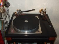
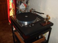
Hi, heres another magneticly suspended tonearm specificaly for a Lenco project, this one fits right on the standard Lenco, and uses the original arm lifter.
The use of a tapered square arm section reduces the amount of turning considerably.
The lower magnet is mounted directly into the height adjustable mounting column, and the upper magnet in a small turned item bolted to the rosewood wand.
I found this method of construction saves a lot of awkward precision turning, and its much quicker to make.
Obviously the arm is awaiting a proper counterweight in the first two pics, but the final pic shows it almost finished mounted on a Lenco.
Still a little bit more final shapeing to do, before i am completley happy with it, buch much simpler and cheaper to make.
Attachments
Wonderful Ideas!
A great looking arm with a different twist, very ingenious. Good craftsmanship with an eye for style. I'm impressed.
I only hope mine looks as good when I'm finished.
BTW, Which Lenco model# is that? and are Lenco's as good as a DIY Teres? Teres within reason of course. I realize we could build a $20,000 Teres clone. I'm asking about a $ for $ comparison.
Ron
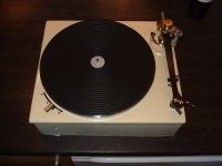
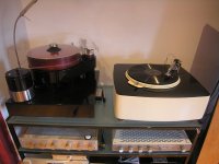
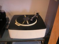
I have a teres 265 clone and a lenco L75 rebuilt into a heavy plinth. Teres edges it out in terms of tone, but to be honest, if I had built the lenco first, I never would have gone for the Teres. I do think though, the lenco needs to be mounted in a heavy damped plinth, with the main plate securely coupled to the plinth and preferably the arm mounted spearately (mine isn't).
I would have loved one of the PTP plates, but missed the boat. I think they would have made this a really top notch table. I think the Lencos are the most under rated table out there, in fact I would advise anyone just to buy one up cos like the garrard, they will only rise in price.
Fran
I would have loved one of the PTP plates, but missed the boat. I think they would have made this a really top notch table. I think the Lencos are the most under rated table out there, in fact I would advise anyone just to buy one up cos like the garrard, they will only rise in price.
Fran
Attachments
Most of the info is burried further back in this thread, which , btw, is an excellent read and contains much more vital info if you're going to build one.
Here's the "Cliffs Notes" version for my sources:
Thread:
100 Feet Vectran Cord, Thread, STRONGER than Kevlar - eBay (item 360183453508 end time Jun-22-10 09:26:00 PDT)
Magnets:
http://www.kjmagnetics.com/proddetail.asp?prod=D63-N52&cat=168
JD
Here's the "Cliffs Notes" version for my sources:
Thread:
100 Feet Vectran Cord, Thread, STRONGER than Kevlar - eBay (item 360183453508 end time Jun-22-10 09:26:00 PDT)
Magnets:
http://www.kjmagnetics.com/proddetail.asp?prod=D63-N52&cat=168
JD
Can I ask 2 cheeky questions about the schroder clones?
Where do you get the string and where do you get the magnets? Please include types/part numbers if possible....
Fran
Last edited:
- Home
- Source & Line
- Analogue Source
- DIY Schroeder Tonearm???