Your life would be SO much easier with an Arduino for the decoder/display driver. Those annoyances that
you'll need to "cut and jumper' to fix would be a software revision. Same story for the 'things you forgot'
in the hardware decoding. That mute between input changes is trivial in software. Display on for preset
or on continuously could be a user setup that you can have either way and set the time in non volatile RAM.
If you can do logic (and it's obvious that you can) you just translate that to code. Once you get past the first
step you will wonder why you didn't do this years ago.
An Arduino board is less that $10 in your hand and the IDE is free. Google the task you want to do and the
odds are high someone did something similar and you only need to download it. That's how I got the shaft
encoder reader and remote decoder to use in my preamp. Then you can tweak to your hearts content.
I would be happy to help get you started.
G²
Thanks for the kind offer however, for me, the whole point of this was to have a project that would allow me to learn about digital circuits and, at the same time, create a design for an analogue pre that I could use in my system. In the OPs original post he sets out the desire to avoid having a microprocessor in the design and that drew me to this as a basis to which I could apply some modifications / additions to get to something that fits my needs.
I absolutely realise that the Arduino route would be far simpler and allow many more features but I'd have learnt far less that way.
Your life would be SO much easier with an Arduino for the decoder/display driver.
100% agree. Arduino is a much better/easier/nicer than PIC, AVR etc.
Once you get past the first step you will wonder why you didn't do this years ago.
I think now days this same "level up" moment is to just use a CircuitPython board. Debugging, the syntax, the file system, use any IDE, auto reloading. It makes the Arduino system look like it's from museum
")
I may have to take a look at this CircuitPython board. I am a programmer as well as a digital designer but for this project I wanted to do digital logic so anyone could just solder and go without having to do the programming, etc. Plus it was a fun project that was used in a commercial system for someone not setup for programming.
I did a similar volume / tape deck controller back in the 80's using CD4066's and two 4040 counters to log the 555 clock.
it does a perfect 80db (10 bit) fade in/out with virtually no distortion.
Today I would use an Arduino cpu to control IR, the chips and input selection and display
it does a perfect 80db (10 bit) fade in/out with virtually no distortion.
Today I would use an Arduino cpu to control IR, the chips and input selection and display
Hey Paulski,
How is your project going? Have you figured out some of the issues with your boards?
I am very curious. Also to you have a part number for the rotary encoder?
Have a good one.
It's funny you should ask as I'm expecting DHL to deliver a new set of boards today! I think that I resolved the issues around the glitching display, it stemmed from propagation delays in the 4040 ripple counter that caused the latch to go high on powers of 2. I'm hoping the new board will resolve this but we'll see... I ended up resigning the debounce circuits for the encoders to use a custom debounce chip (the MC14490) as, even with some modifications I was still getting some slightly erratic volume / input selection changes. Hopefully this will work better.
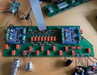
I also designed the input selection / volume board which I'll build first as the existing boards should work with this regardless of the issues. This uses two of Tom Christiansen's universal buffer boards that will mount on the board I've designed. This allows me to have balanced and single-ended inputs and outputs with the volume section being purely single-ended. Half the resistors and relays needed!
It's going to take me a few days to get all this built up, I'll update with some pictures in due course.
Last edited:
I was just having some fun looking into idea for a rotary up/down volume control. Found a chip that vastly simplifies the circuit, a rotary encoder into a LS7083 from www.usdigital.com, into the up/down counter. piece of cake.
Have a good one.
Have a good one.
Hi Samoloko,
I will see if the Audiophile equipment manufacturer that used the first design is interested. It would require a change to the front panel so he might not be interested.
While I could change the design so it could be either, right now and am still building a house which is almost done but until then I wouldn't be able to layout a new PCB and test it. Without testing I am reluctant to release any major changes. if someone really wants to test a new design then I can update a schematic and do gerbers.
Well my friend who is the audio business owner likes the idea of the rotary encoder for volume. I also found that the encoder can be had with a momentary contact switch so I could make it that you push the rotary switch to mute, push again to unmute, rotate for up or down volume. So when I have some time I will do a schematic and lay out some PCBs. I will make the one main board into three, analog, digital, and PSU. So the analog and digital boards can be stacked to take up less space inside a preamp.
John,
thank you very much
appreciate very much your effort and generosity
would you please clarify If rotary encoder Is part of bigger main board or from separate pcb
when rotary encoder Is ready please count me for at least two balanced pcb sets to order from you
thank you very much
appreciate very much your effort and generosity
would you please clarify If rotary encoder Is part of bigger main board or from separate pcb
when rotary encoder Is ready please count me for at least two balanced pcb sets to order from you
Last edited:
So I've now got a complete system up and running on the bench as I've built up the relay / selection board. It works after I discovered a fundamental error - I reversed the order of the 8 bits that control the volume relays! Fortunately there's an easy fix for this - reverse the order of the resistors so I got a bit lucky really.
Before I discovered the cause of the error I was puzzling over why I was getting strange reading for the resistor network when changing the volume values, whilst doing this I noticed something about the circuit I'd not realised before - at all volume values over 0 the signal is connected to ground via the resistors whose relays are off. So at vol=0 the input effectively sees infinite impedance but as soon as that's advanced to 1 it's connected to the output via the 8K LSB resistor BUT it's also connected to ground via the 7 other resistors. In parallel these make a 31R resistor. Obviously this changes for each volume value but it's clear that the input is going to be quite heavily loaded. After debating an R2R circuit I'd effectively copied the original circuit and wondered if I'd made a mistake somewhere. I checked your original circuit and see it follows the same principal - was this intentional? Or have I missed something?
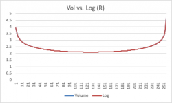
Compared to an R2R or a simple volume pot which both present a near constant impedance to the source this circuit presents a constantly changing impedance from infinite to as low as around 124R and back to something approximating the impedance of the connected output. The graph attached shows the change in (the log of) impedance as volume changes.
Before I discovered the cause of the error I was puzzling over why I was getting strange reading for the resistor network when changing the volume values, whilst doing this I noticed something about the circuit I'd not realised before - at all volume values over 0 the signal is connected to ground via the resistors whose relays are off. So at vol=0 the input effectively sees infinite impedance but as soon as that's advanced to 1 it's connected to the output via the 8K LSB resistor BUT it's also connected to ground via the 7 other resistors. In parallel these make a 31R resistor. Obviously this changes for each volume value but it's clear that the input is going to be quite heavily loaded. After debating an R2R circuit I'd effectively copied the original circuit and wondered if I'd made a mistake somewhere. I checked your original circuit and see it follows the same principal - was this intentional? Or have I missed something?
Compared to an R2R or a simple volume pot which both present a near constant impedance to the source this circuit presents a constantly changing impedance from infinite to as low as around 124R and back to something approximating the impedance of the connected output. The graph attached shows the change in (the log of) impedance as volume changes.
Attachments
Last edited:
So ignoring how hard a load this might present to an input this causes me an issue as I'd added an AV bypass circuit. This simply bypasses the volume resistors BUT, as I now realise the signal will still be connected to ground via whichever combination of resistors do not have their relays active. So, at low volume settings this resistance is low enough to cause the buffer to go into clipping at levels of around 2.5V pk to pk. Therefore if I select AV bypass and the volume is set low enough the output could be clipped which i guess shows the buffer I'm using has reached its limit. I need to do some more thinking on this as I'm concerned I may have to do a redesign of the relay board.
to Samoloko, the rotary encoder would be on the Display board. The main board doesn't change design, just thinking of making it two boards to stack and a separate power supply board.
To Paulski, the resistor layout is copied from my Pass Aleph P preamp, since it is very neutral sounding I didn't want to reinvent the wheel. Most of my source equipment has very low output impedance and can drive the lower impedances without a problem.
To Paulski, the resistor layout is copied from my Pass Aleph P preamp, since it is very neutral sounding I didn't want to reinvent the wheel. Most of my source equipment has very low output impedance and can drive the lower impedances without a problem.
To Paulski, the resistor layout is copied from my Pass Aleph P preamp, since it is very neutral sounding I didn't want to reinvent the wheel. Most of my source equipment has very low output impedance and can drive the lower impedances without a problem.
Ah, it’s not really your source equipment that’s untroubled by the low impedance it’s the input circuit in the Aleph P that can drive such low loads. On reflection I think the this volume control is not really suited for general use unless the circuit driving it is intended for such a purpose. I’ll look at modifying it to suit my need better, I’m very close to a fully functional preamp, I may actually try it as is just to see how it sounds!
The more I think about this the more I'm annoyed with myself for not looking at the volume circuit in more detail before using it. This is not a dig at the OP but the circuit is not suitable for general preamp use as there's pretty much nothing that drive a line level into 30R without, at the very least, a big jump in distortion levels. It might very well work within the context of the Aleph P circuitry but it doesn't really have an application outside of that unless you use a very specific buffer to drive it that's designed to drive such a low load. I'd advise anyone contemplating using this to consider very carefully the system it will integrate into.
FWIW the Nurochrome buffer I'm using in my design has a good go at driving it but Tom advises that anything much below 1k will lead to rising distortion so it won't be giving its best.
FWIW the Nurochrome buffer I'm using in my design has a good go at driving it but Tom advises that anything much below 1k will lead to rising distortion so it won't be giving its best.
At least with this circuit it is a simple matter to change the resistor values. I am working on a spreadsheet to calculate possible better values that most source outputs can drive. It may take a while as there are 256 steps.
That’s true, there’s room for manoeuvre but the issue with increasing the values maybe be that, ironically, if you aim for, say, 1K as a minimum load you may end up with too much impedance at low volume settings!
Another alternative might be to increase the values and settle for just 64 volume steps. This would take out the two resistors with the lowest value and that immediately increases the lowest impedance by a factor of about 4. Obviously strange things would happen at volume settings above 64 without a design change in the logic section.
I have a spreadsheet that might help with R values, let me know if you’d like a copy.
Last edited:
I had already created a spreadsheet which isn't elegant but does the job. I still would be interested in your spreadsheet.
Anyways, the volume control is essentially a voltage divider with the source connected to say the top of resistor A and the other side of resistor A is tied to resistor B which is in turn tied to ground with the output taken from the junction of A and B. The switching parallels other resistors with A or B.
Using the last values I suggested of 20K, 10k, 5K, 2.5K, 1.25k, 625, 312, and 156 the lowest volume setting of A over B is 20K over 79 ohms for a load of 20079 ohms to the source, pretty much the same at the second to top volume step 79 ohms over 20k. The fully volume step is all resistors in parallel with each other (minimum resistance) and in series between the source and the buffer. It is at the middle step (128) that the lowest/worst load is 157 over 125 for a load of 282 ohms. My equipment can handle that but some may not.
But that is using resistor stepping by half each time but how about using some other divider like 0.707, to pull a figure out of the air. That would give you resistor values of 20k, 14.14K, 10k, 7.06K, 5k, 3.5k 1.76k, and 1.25k or the closest standard values. This gives low volume of 20k over 460 ohm, and inverse for the next to highest setting. The worst case load is moved up but at half volume 708 over 125 ohm or a load of 833 ohm. No too bad.
How linear this would be I haven't look at, not until I finish building the house and have a sound room again, but with 256 steps I am sure there would be a Goldilocks setting.
So incremental encoders and different resistor values to play with in the future. Also want to try a balanced Silicon Carbide MOSFET amp in the Burning Amp 3 style.
Last edited:
- Home
- Source & Line
- Analog Line Level
- Preamp Control - Volume, input, mute, remote