That is correct, the display only displays where the volume counters on the main board, U6 and U7, are set to. The display is continuously clock up by an oscillator circuit, U12/R3/C5, on the main board fed to U7 and daisy chained to U6 the U5 on the display board. The unused clock lines, down, should not be left floating so are tied to ground. The output of the comparator circuit, U15 and U16 on the main board, reads the volume counter and display counter, U14, when they are the same it trigger the one-shot U18 whos output is fed to the display chips and latches the current count of the display chips to the output to show on the LEDs displays. Not sure if this is covered in the first post, or later trouble shooting post, though it isn't easy to explain you just have to study the schematic with the overview. Let me know if I need to help clarify any more.
That is correct, the display only displays where the volume counters on the main board, U6 and U7, are set to. The display is continuously clock up by an oscillator circuit, U12/R3/C5, on the main board fed to U7 and daisy chained to U6 the U5 on the display board. The unused clock lines, down, should not be left floating so are tied to ground. The output of the comparator circuit, U15 and U16 on the main board, reads the volume counter and display counter, U14, when they are the same it trigger the one-shot U18 whos output is fed to the display chips and latches the current count of the display chips to the output to show on the LEDs displays. Not sure if this is covered in the first post, or later trouble shooting post, though it isn't easy to explain you just have to study the schematic with the overview. Let me know if I need to help clarify any more.
That's perfect, I get it now. Thanks for clarifying.
By the way, I'm trying to create an implementation of your design with some subtle changes - I plan to use rotary encoders rather than push buttons for volume / input selection. I'll use an encoder with a push button for the mute command. Also I want to split the main logic board into logic and switching so effectively having a separate board with the relays for selection / volume and a separate board for the logic. For me the 12" by 7" main board is a little unwieldy. Obviously I'll update in due course as I progress.
Sounds interesting, you could do away with the 7555 chip in the "helper" circuit then also, but I haven't priced out a rotary encoders to see the overall cost difference.
I am working on a single ended 4 input version of the boards now with the power supply split off to a separate board and separating the main board into two, as you say, one analog one digital, so they can be stacked and take up much less space. Later, if I need another project I will take the current main Board, V5, and make it two boards and stackable.
It will be interesting to see your implementation. Have fun.
Hey Paulski,
I looked at Mouser for Rotary optical encoders and the cheapest one I found was around $50, where as the push button and debounce circuit is around $1. Do you have a less expensive option?
I looked at Mouser for Rotary optical encoders and the cheapest one I found was around $50, where as the push button and debounce circuit is around $1. Do you have a less expensive option?
I’ve already tested a mechanical encoder with a flip flop / debounce circuit and it looks to be generating a nice clean pulse train. I’ve ordered some prototype PCBs to test this more thoroughly but it looks like this will allow a £1/ $1 encoder plus a few cheap components to do the job. More to follow.
For the Request of SRMcGee I have created another set of boards for a 4 input Single Ended, Digital Volume, Input selection, Mute, with a Remote, I will start a new thread so I can know which of the three designs we are talking about now. See 4 Input SE Volume, Mute, Remote
John,
thank you for this open project
does final test to all V5 balanced pre amp pcbs OK
how much would cost full set V5 pcbs
thank you for this open project
does final test to all V5 balanced pre amp pcbs OK
how much would cost full set V5 pcbs
Version 5 is the latest version of the main board which is just a new one-shot design which I tested in another project so it should be good. Buying a minimum lot of 5 from a China manufacturer is $80 USD or $15 USD each. The remote you can get 5 boards made for $5. The display would be somewhere in between.
So I have a request to buy PCBs for this project. Anyone else interested in a set? If we have at least 4 others then I will purchase a set and sell them individually.
I'd be interested in a set for a full balanced stereo setup. What would the total be on that?
Thanks in advance!
Thanks in advance!
I am just guesstimating but $30 to $40 USD for a set of three boards, so we just need a couple more people to commit to have a group buy.
So I entered the PCB sizes into the cost estimator from my favorite Chinese PCB manufacturer and came up with a set of 10 of all three board with shipping to the US for $125 or $12.50 for each set. plus shipping from California to wherever.
perfect - at that price I would like 2 pcs
John, It can be useful to post In GB section
regards
John, It can be useful to post In GB section
regards
As I mentioned some time ago I was looking at the possibility of modifying the original design here to use rotary encoders to provide something more 'analogue' as a control interface. I very quickly came up with this circuit to debounce and detect the direction of rotation. This provides nice clean pulses for volume input up/down plus a mute on/off using the push button function of one of the decoders:
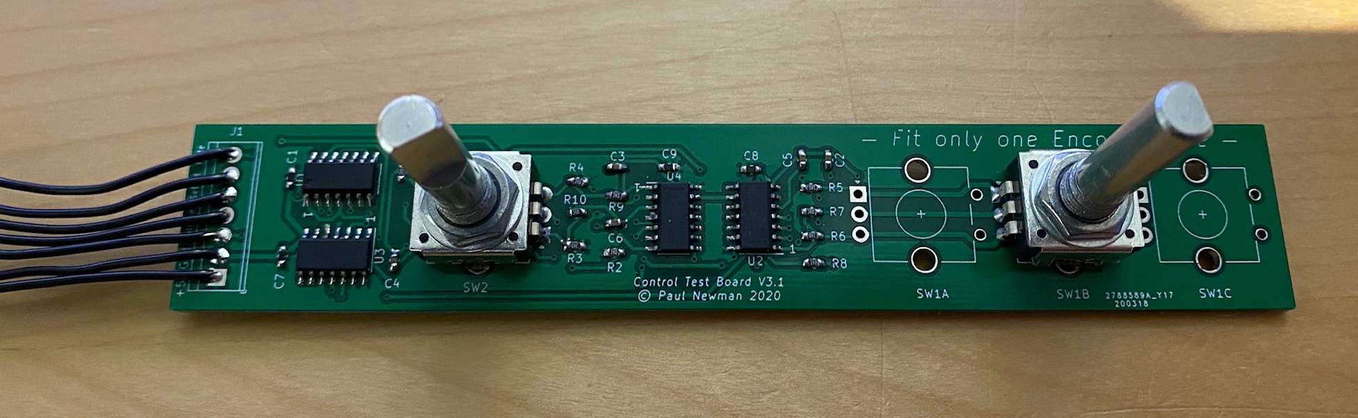
The schematic for that is attached below.
The schematic for that is attached below.
Attachments
So my plan then was to incorporate this into John's original design with a few other tweaks, namely:
I've completed the design and build of the display board and main logic board together with a small test board that imitates the relays by indicating the status of the outputs and it's largely functional but I have a few issues I'm struggling with. This is what the boards look like:
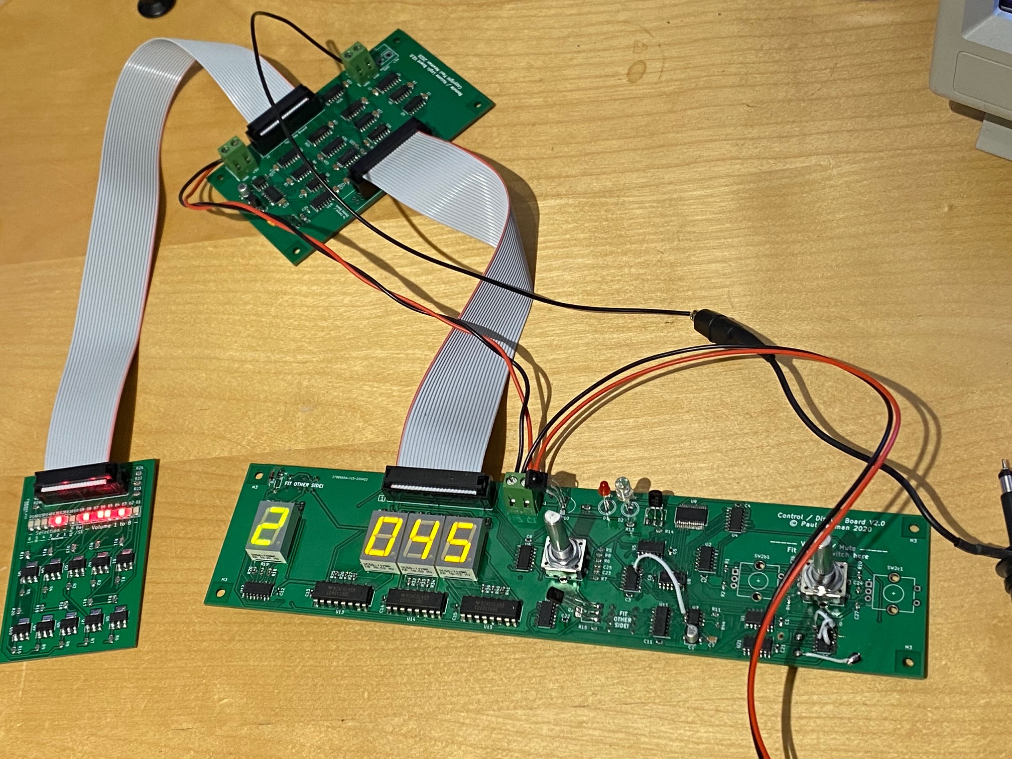
The display board was always going to be a prototype hence the positions of certain components are sub-optimal. Also you'll note some hacking where I had to resolve some daft schematic errors that got translated into the PCB. The schematics are attached below for the two larger boards.
- Drastically reduce the size of the main board by splitting the relay section to a separate board (to be located close to the inputs and outputs)
- Add a timer circuit that would switch the displays off after a pre-determined time with the option for always on
- Adding a brief mute when switching between inputs
- Adding an output that indicates whether an input is balanced or S/E. The purpose of this is to potentially allow me to use with the Neurochrome buffer board created by Tom Christiansen (this board can be switched between balanced and S/E operation using a jumper).
- Add a mute and display on function to the remote control
- Use SMT parts where possible
I've completed the design and build of the display board and main logic board together with a small test board that imitates the relays by indicating the status of the outputs and it's largely functional but I have a few issues I'm struggling with. This is what the boards look like:
The display board was always going to be a prototype hence the positions of certain components are sub-optimal. Also you'll note some hacking where I had to resolve some daft schematic errors that got translated into the PCB. The schematics are attached below for the two larger boards.
Attachments
Last edited:
Essentially the system works but there are some issues:
Those said when the system has an input and volume selected it's rock solid stable and will stay in that state indefinitely.
I've been on a steep curve with this as digital electronics is not really my thing and these are pretty much the first PCBs I've designed so I had to learn KiCad as well to get to this point. It's frustrating as it's a case of close but yet so far. I've run out of ideas to resolve these problems. It could be that my board layout is causing the issues but my digital skills are limited in that respect.
The one issue that is really bugging me is the first in the list. Using my scope I can see nice clean pulses coming from the circuit that debounces etc. the encoders those same clean pulses arrive at the logic board. Why a single pulse from this causes multiple steps is a mystery, it doesn't happen when using the remote.
- Using the rotary encoders causes the volume / input to go up or down in steps of more than one.
- When the volume level reaches 000 the display flickers as though it's cycling through several values. it also starts in this state.
- Sometimes the volume display shows the correct values but segments of the display that should not be on flicker at somewhere around 12Hz
Those said when the system has an input and volume selected it's rock solid stable and will stay in that state indefinitely.
I've been on a steep curve with this as digital electronics is not really my thing and these are pretty much the first PCBs I've designed so I had to learn KiCad as well to get to this point. It's frustrating as it's a case of close but yet so far. I've run out of ideas to resolve these problems. It could be that my board layout is causing the issues but my digital skills are limited in that respect.
The one issue that is really bugging me is the first in the list. Using my scope I can see nice clean pulses coming from the circuit that debounces etc. the encoders those same clean pulses arrive at the logic board. Why a single pulse from this causes multiple steps is a mystery, it doesn't happen when using the remote.
In the meantime I've started work on a revised display board that has the positions of various components corrected to allow the board to be mounted to a front panel and also corrects my original errors. I've also started the relay board but I can't get either of these sent for production until I figure out the issues I've currently got. Any ideas gratefully received!
So my plan then was to incorporate this into John's original design with a few other tweaks, namely:
1: Drastically reduce the size of the main board by splitting the relay section to a separate board (to be located close to the inputs and outputs)
2: Add a timer circuit that would switch the displays off after a pre-determined time with the option for always on
3: Adding a brief mute when switching between inputs
4: Adding an output that indicates whether an input is balanced or S/E. The purpose of this is to potentially allow me to use with the <snip>
Your life would be SO much easier with an Arduino for the decoder/display driver. Those annoyances that
you'll need to "cut and jumper' to fix would be a software revision. Same story for the 'things you forgot'
in the hardware decoding. That mute between input changes is trivial in software. Display on for preset
or on continuously could be a user setup that you can have either way and set the time in non volatile RAM.
If you can do logic (and it's obvious that you can) you just translate that to code. Once you get past the first
step you will wonder why you didn't do this years ago.
An Arduino board is less that $10 in your hand and the IDE is free. Google the task you want to do and the
odds are high someone did something similar and you only need to download it. That's how I got the shaft
encoder reader and remote decoder to use in my preamp. Then you can tweak to your hearts content.
I would be happy to help get you started.
G²
- Home
- Source & Line
- Analog Line Level
- Preamp Control - Volume, input, mute, remote