"The BBB sounds like an interesting project! "
It could be! I have a BBB with a nice Hi rez touchscreen. The cost is $120 for the pair.
It could be! I have a BBB with a nice Hi rez touchscreen. The cost is $120 for the pair.
Hi Carl,
I have written this code in BASCOM-AVR for the Atmel mega/xmega. But the hardware can run any code from a compiler like Ardunio or gcc. I did this using a 4x40 LCD character display, since I am not a very good programmer, so try to make it simple. When you get into graphics displays then the real work begins with managing that aspect. I got as far as getting IR remotes to work and even made my own remote. Getting into have a cell phone control is yet another step up. It turns into one heck of a lot of code to do some pretty simple functions such as change the channel, vol up/down. If you want power on/off you need an auxillary PS or a MCU in sleep mode running off a super cap. Lots of options. Have fun
Rick
I find the BBB approach interesting. We can make the system a media player, if we add a network interface.
I know Carl didn't ask this, but I'm more interested in adding modules to make this preamp a digital+analog preamp. I would like to add a DAC (and I think my idea can be implemented without having to choose a specific DAC board) and digital inputs (at least 3), with each input being switchable either coax or Toslink. And I'd like the front panel input selector rotary switch to let me switch among digital and analog inputs seamlessly.
I feel a pure analog preamp is a little limited in today's context, and a DIY DAC + preamp is more useful.
Another option that might be worth looking at would be an ESP32. They have built in Ethernet and Bluetooth and are pretty powerful for only a few dollars. They are easy to program and there's lots of available examples to start from.
If anyone wants to add a music server, look at Arylic. Cheap and already has a nice network interface.
If anyone wants to add a music server, look at Arylic. Cheap and already has a nice network interface.
"Another option that might be worth looking at would be an ESP32...."
I am continuously amazed at how fast the cheap embedded processor market is changing. I struggle to keep up.
I am continuously amazed at how fast the cheap embedded processor market is changing. I struggle to keep up.
I have been working with Arduino Nano to run the remote control. so far I have been able to do the volume control (bourns motorpot), source selection and startup delay. Still working on implementing the mute switch. I plan to add a oled for display which should not present lot of issues. There are plenty of examples on the web and one can easily modify the code. All of this can be done without any major modifications to the existing selector pcb. I am replacing the mechanical selector with the remote board with all connection remaining the same.
Dinesh
Dinesh
Dinesh,
I like your approach. The more I look at the BBB, the more that I question whether or not it is a good fit. My current mindset is to take an approach like yours and use a small motherboard in a separate chassis to do all of the DSP processing that I want to play with. I invite you to share your project on this thread.
I like your approach. The more I look at the BBB, the more that I question whether or not it is a good fit. My current mindset is to take an approach like yours and use a small motherboard in a separate chassis to do all of the DSP processing that I want to play with. I invite you to share your project on this thread.
Last edited:
If I may throw my 5 cents into the topic:
This preamp is a wonderful example of an easy-to-build, high performance, low distortion piece of hardware. 😎
Bringing high power controllers (like ARM chips, e.g. Raspberries or BBBs) into an audio device, there is always the challenge to keep distortion low and I doubt it is possible to do it with this preamp without audibly degrading its audio performance.
To make it short:
I also like Dinesh's approach with an IR remote and a small microcontroller (Atmel=easy tu use, Pic=cheaper). A DAC or streaming client or whatever else should peacefully reside in a different enclosure 😉
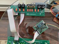
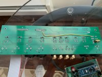
Finally, I have a working micro-controller doing all the remote duties - channel selection, mute, volume (motor pot) and a 3 second delay at startup. For mute and delay startup, I didn't populate any of the circuit on the selector board. I added a wire from the collector of the bottom transistor to the unused pin (#7) on the selector PCB. This is the ground of the output relays which the microcontroller would do the delay startup and mute tasks. For the channel relays, I had a problem since we are switching +12v on the selector PCB. I ended up building a transistor invertor (NOT gate) using NPN followed by a PNP transistor to give full +12v to the relay. If the selector PCB were switching grounds, one transistor or even a ULN2003 could have been used. The mute circuit is a standard NPN transistor driver as we are only switching grounds. For the volume pot, I used a h-bridge to drive it. The microcontroller will be using a separate 5V power.
The source code I modified can be found at : GitHub - gkiranps/gArduinoRemote
The program can be modified to be used with any remote you have lying around.
I still need to add either a encoder or switches on the panel for source selection.
I almost forgot, the preamp sounds great ! Thanks to Doug and Carl for making available such a beautiful design.
Thanks,
Dinesh
Attachments
Hi Dinesh,
thank you for sharing your approach with us!
I am sure that both, wiring and the repo will be helpful for many people 🙂
Some thoughts (please keep in mind that I'm not a pro):
thank you for sharing your approach with us!
I am sure that both, wiring and the repo will be helpful for many people 🙂
Some thoughts (please keep in mind that I'm not a pro):
- I don't know how you provide the supply for the Arduino. But I guess that if you could hook the Arduino's ground to the 12V (not the 15V line!) line of the input pcb, you would get along with just one transistor per relay.
- Another approach would be to use optocouplers instead of transistors.
- Maybe you could use that jumper named "12V SW" on the input pcb for your mute switching. You wouldn't need to solder the jumper wire that you use for the mute control. But this line has 15V, so saving the jumper wire would cost 2 more transistors - maybe not such a good idea 😉 On the other hand, if you decide to use an ULN2003, because you hooked up on the 12V line with Arduino GND, then you have one of the Darlington's left over, anyway...
oodi said "Are boards available for this?"
oodi,
Please check your personal messages. I just sent you one.
oodi,
Please check your personal messages. I just sent you one.
"Bummer.... I was eagerly awaiting your answer to oodi's question..... "
Ha, ha ...
I still have a few. Personal message me if you want the details
Ha, ha ...
I still have a few. Personal message me if you want the details
Hi All,
Sorry if this is a stupid idea...
But if I only wanted unbalanced inputs can I do this:
Input1.jpg - Google Drive
?
I don't quite understand the unbalanced input. It seems to leave XLR pin 3 just hanging in the air? or does it get grounded by the relay on the input board?
Regards, MFW
Sorry if this is a stupid idea...
But if I only wanted unbalanced inputs can I do this:
Input1.jpg - Google Drive
?
I don't quite understand the unbalanced input. It seems to leave XLR pin 3 just hanging in the air? or does it get grounded by the relay on the input board?
Regards, MFW
Last edited:
> if I only wanted unbalanced inputs can I .....
?? That's like modifying TV's Batmobile into a Ford Galaxie. Take off a lot of fancy-stuff. Doug Self shows unbalanced inputs earlier in the book. While the book is copyrighted, this circuit and values are not critical or original. At "C", if input levels are huge, make R2 a pot; if signals are happy size but there is a need to fade to silence, make R4 a pot.
?? That's like modifying TV's Batmobile into a Ford Galaxie. Take off a lot of fancy-stuff. Doug Self shows unbalanced inputs earlier in the book. While the book is copyrighted, this circuit and values are not critical or original. At "C", if input levels are huge, make R2 a pot; if signals are happy size but there is a need to fade to silence, make R4 a pot.
Attachments
C: As a general rule, attenuation should only take place on the volume control.> if I only wanted unbalanced inputs can I .....
At "C", if input levels are huge, make R2 a pot; if signals are happy size but there is a need to fade to silence, make R4 a pot.
B: First attenuataion then amplification. Bad thing! Isn't it?
- Home
- Source & Line
- Analog Line Level
- Doug Self Preamp from Linear Audio #5