glenv6,
Here is a rear panel layout for a 1U case. I cannot remember who sent it to me, so thank you whoever you are.
Dropbox - REAR_PANEL_1U.fpd - Simplify your life
Thanks Carl!
Appreciate that, thanks!
Enhanced I/O help please
Wondering if anyone else has encountered this or can provide guidance.
I think (?) I have the latest version of Carl's IO board (has the signal diodes on top, just below the relays).
I am consistently getting 14.8 V downstream from the 12V regulator (17V at the input), and just a bit over 15V across the 1N4148.
It seems like the regulator is damaged, but is there anything else to consider before changing it?
Thanks.
Hi Johnny - there was some discussion about the 78L12 possibly being unstable without caps on the input and output side - starting around post #1058, here:
https://www.diyaudio.com/forums/ana...-preamp-linear-audio-5-a-106.html#post5490511
There are some recommendations in the following threads about adding caps, and values to use. I think put the caps from the App note (TI?) on the underside of the board.
PaulF
https://www.diyaudio.com/forums/ana...-preamp-linear-audio-5-a-106.html#post5490511
There are some recommendations in the following threads about adding caps, and values to use. I think put the caps from the App note (TI?) on the underside of the board.
PaulF
Thanks very much Paulf.
I'll check for oscillation - the smd caps look like a simple solution.
Cheers!
If it helps, here is the one I used..
TAP226K035CCS
Thanks fvzeppelin, that's a good idea and easier to find something close to TI's indicated capacitance.Soldering a small tht tantalum on the bottom side is as easy.
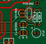
Thanks Carl, my board doesn't have space for a decoupling cap so I guess not quite the latest version.PLEASE NOTE: The latest IO PCBs have a place for a decoupling capacitor. It is circled in red immediately behind the 12 volt regulator.
Thanks glenv6 - that's a good selection. Question though, is there a reason to use 22 uF rather than 10uF, or did you just have this value in your parts box?If it helps, here is the one I used..
TAP226K035CCS
Thanks glenv6 - that's a good selection. Question though, is there a reason to use 22 uF rather than 10uF, or did you just have this value in your parts box?
Correct, I had one in the parts bin and freecrowder had already proven that value to work…
https://www.diyaudio.com/forums/ana...-preamp-linear-audio-5-a-121.html#post5571326
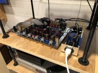
Thanks again Carl for your designs. I modified your 1U design to better fit a 2U case (just my preference), but before I order a case, I decided to spend some quality time listening to it.
I really like this preamp! As I said in a previous post, this thing is quiet. And it sounds very good - the soundstage is the best of my three preamps. The other two are a vintage NAD 1600 I bought brand new decades ago, and the Wayne Coburn 2018 I built last year. The NAD is warm, transparent, and a little on the restrained side. The WC2018 is clear, clean and spectacularly detailed. This DS/CH preamp is somewhere between those two, but the soundstage really sets it apart. Instruments and vocals are suspended in specific separate locations across a wide stage. Music is well, musical and enjoyable. I have listened for hours without the magic of that soundstage wearing off.
So, I will be ordering a case and boxing this thing up ASAP. It will probably spend more time in my rack than the other two.
Thanks again Carl for making Doug’s excellent design a reality!
Attachments
Looks great Glenv6. Be sure to post PICs of what it looks like in it's new enclosure.
I will Carl, thanks!
Glen
I would add a note of caution with respect to tantalum capacitors. Companies such as IBM and Hewlett Packard long ago prohibited their usage in designs. Their chemistry makes them prone to combustion, and tantalum is also considered a conflict mineral. As a design engineer, it was always possible to use ceramic or solid electrolyte capacitors in their place. Usage of tantalum polymer capacitors solves the ignition problem for low impedance power rail applications, and ceramic capacitors were generally recommended for regulator stability applications.
Any reason to choose a tantalum over an aluminum electrolytic or an X7R ceramic cap for decoupling that regulator?
In regards to main power entry, is there a preferred type of filtered IEC receptacle for the preamp? I don't think I need one with a switch (I prefer a power on/off switch on the front of a preamp, so I don't see the point in a second one at the rear).
Also, has anyone drawn a diagram of their grounding scheme?
Cheers!
Last edited:
You might want to consider an IEC inlet with an integral fuse. Although I am sure none of our builds is going to be submitted for Safety certification by an agency such as UL, CSA, TUV or similar, we should build them as if they were. We want them to be safe. There are requirements for spacing between Line and Neutral, and Line/Neutral and Earthed metal. If these spacing requirements are not met by the design, the Safety agency will short them, and note the result. It had best be that the fuse blows. If the spacing in question is before the fuse, you are relying on the breaker of the circuit you are powered from to trip. "Trip", as in "trip before a fire starts". If you do not want to rely on an unknown breaker, it is best to design the equipment such that you are relying on the fuse you put in the equipment. If the fuse is part of the IEC inlet, it follows that any short that could happen is "after" the fuse, and the fuse can be appropriately chosen to open before a fire starts. Make sense? Especially if you do not know what the required creepage spacings, clearance distances and insulation requirements are: put a fuse in the IEC inlet. The Fates may smile upon you...
I certainly agree that a fused entry is needed, although the power supply’s input side is fused.
I guess my questions around this are:
1. What fuse amperage rating is needed for this preamp powered by North American 115-120V?
2. There’s a plethora of RFI filtered IEC entry receptacles available. I’m not sure which one is proper for this application, as there are at least two criteria. The filters are designed for optimal attenuation within their specified current range, and there are different MHz targets. I’m surely overthinking it, but I figure I might as well ask and do it correctly.
Speaking solely to the frequency range of attenuation on the input filter. Lower is better, but more expensive (larger coils and/or capacitors).
A separate but related topic: I personally prefer the apparent European standard of using a power switch to switch both hot and neutral of the incoming AC power (i.e., a double pole switch). This decreases the risk of a short.
A separate but related topic: I personally prefer the apparent European standard of using a power switch to switch both hot and neutral of the incoming AC power (i.e., a double pole switch). This decreases the risk of a short.
I think the filters integrated into IEC inlets are more intended for IT equipment with switching power supplies. The conducted emissions they are intended to suppress are from 150kHz to 30MHz. The question then is would they be of use in keeping such noise out of a preamp? I would ask if anyone knows of filters being used in high end audio equipment? The equipment I have does not use filtering on their AC inputs, but my sample size is very small.
- Home
- Source & Line
- Analog Line Level
- Doug Self Preamp from Linear Audio #5