Finished Parameter implementation.
Documentation snippet:
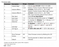
Optional parameters can be set by pressing the infrared remote key “0” three times within 2 seconds to go into parameter mode. This is acknowledged by 3-time blinking of the LED.
To set a parameter, the parameter ID must first be selected from the table below. The parameter value is entered in 3 digits. The parameters are then permanently stored in the flash of the microcontroller. This is acknowledged by 4-time blinking of the LED.
Cancellation is possible at any time by pressing the rotary-encoder button continuously for 3 seconds, this is confirmed by the LED flashing 5 times.
To set all parameters to default values, use parameter id “9” and value “999”.
Example: Set “Volume Offset L” to 12
1. Press key “0” three times
2. Press key “2” (Volume Offset L)
3. Press key “0”
4. Press key “1”
5. Press key “2”
Documentation snippet:
Optional parameters can be set by pressing the infrared remote key “0” three times within 2 seconds to go into parameter mode. This is acknowledged by 3-time blinking of the LED.
To set a parameter, the parameter ID must first be selected from the table below. The parameter value is entered in 3 digits. The parameters are then permanently stored in the flash of the microcontroller. This is acknowledged by 4-time blinking of the LED.
Cancellation is possible at any time by pressing the rotary-encoder button continuously for 3 seconds, this is confirmed by the LED flashing 5 times.
To set all parameters to default values, use parameter id “9” and value “999”.
Example: Set “Volume Offset L” to 12
1. Press key “0” three times
2. Press key “2” (Volume Offset L)
3. Press key “0”
4. Press key “1”
5. Press key “2”
Attachments
OK... is the display an option or won't it be?
With all these features it could be nice to know where you stand by a glance, so one wish it, eventhough a later add-on?
MFG
Claude
With all these features it could be nice to know where you stand by a glance, so one wish it, eventhough a later add-on?
MFG
Claude
@meldano I’d love to use your new version as a pure volume control for balanced XLR input. No source selector, no screen. Would it be possible to do so?
Hi, I see the use of DC/DC converters i.e. "switchers". Please note that this device will perform as well as its power supply more than your usual device because it is a sensitive volume control. My advice is to use a symmetric mini ultra low noise PSU for absolute best results. 78xx/79xx and LM317/337 will get the job done but there are better regs available. Some excellent like LT3045 and LT3094 and some acceptable like for instance TPS7A4901 and TPS7A3001. Power consumption of the device is minimal and so the PSU can be very small as well.
Using a mediocre PSU somewhat defies the sense of building an excellent volume control...
I just added LT3045/3094 supply to mine. The preamp has a regulated LM317/337 which is stepped down to 18V using 78xx regs, then into the new low noise supply. Still need to listen.
I like these ultra low noise regs in combination with the muses.
For other audio circuits I didn’t like the TPS7 or LT30.
BTW: My Muses v2 works fine and I will order the input selector boards to the end of this week.
For other audio circuits I didn’t like the TPS7 or LT30.
BTW: My Muses v2 works fine and I will order the input selector boards to the end of this week.
Hi,
Wondering what is the lowest voltage the "first" muses 73230 kit from meldano can run fine? Its been somewhat finished for a long time but have not testet it yet. Tried with psu +-10v yesterday (was what I had) and did not fire up it seems.
EDIT: Seems as if I got an answer in the other thread
Wondering what is the lowest voltage the "first" muses 73230 kit from meldano can run fine? Its been somewhat finished for a long time but have not testet it yet. Tried with psu +-10v yesterday (was what I had) and did not fire up it seems.
EDIT: Seems as if I got an answer in the other thread
Last edited:
Hi, still trying. Found a decent PSU and doing some initial tests.
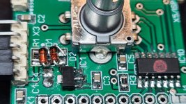
approx +-14Vdc in. However R1=100ohm on the controller board get extremely hot. (actually so hot the solder smelted) Also the 5v LDO gets hot. https://no.mouser.com/ProductDetail...f//tDZEZckA==&countrycode=NO¤cycode=NOK
I do not get 5V out of it. (0.7V) Approx 1.2V enter the LDO.
D1 and D2 are https://no.mouser.com/ProductDetail...8aNy7/u4kVw==&countrycode=NO¤cycode=NOK
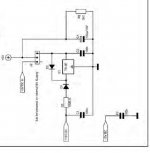
Been tracing "everything" according to schematics. Unable to find what is wrong. Dont think I have reversed D1 and D2...
approx +-14Vdc in. However R1=100ohm on the controller board get extremely hot. (actually so hot the solder smelted) Also the 5v LDO gets hot. https://no.mouser.com/ProductDetail...f//tDZEZckA==&countrycode=NO¤cycode=NOK
I do not get 5V out of it. (0.7V) Approx 1.2V enter the LDO.
D1 and D2 are https://no.mouser.com/ProductDetail...8aNy7/u4kVw==&countrycode=NO¤cycode=NOK
Been tracing "everything" according to schematics. Unable to find what is wrong. Dont think I have reversed D1 and D2...
Do you mean that you measure 1.2v at the regulator input?Hi, still trying. Found a decent PSU and doing some initial tests.
approx +-14Vdc in. However R1=100ohm on the controller board get extremely hot. (actually so hot the solder smelted) Also the 5v LDO gets hot. https://no.mouser.com/ProductDetail...f//tDZEZckA==&countrycode=NO¤cycode=NOK
I do not get 5V out of it. (0.7V) Approx 1.2V enter the LDO.
D1 and D2 are https://no.mouser.com/ProductDetail...8aNy7/u4kVw==&countrycode=NO¤cycode=NOK
Been tracing "everything" according to schematics. Unable to find what is wrong. Dont think I have reversed D1 and D2...
Yes, something like that. Maybe it was a bit less. Switched off very quick because of smoke around that r1=100r resistor
Sorry about the crosspost. Dont like it either but was not sure where to ask.
Will do some more digging later tonight
Sorry about the crosspost. Dont like it either but was not sure where to ask.
Will do some more digging later tonight
I think that regulator is death...
Have a look at diodes. Measure for pass no pass using your multimeter diode test. Are you shure for correct orientation?
Have a look at diodes. Measure for pass no pass using your multimeter diode test. Are you shure for correct orientation?
Diodes are ok. Changed just to be sure, but did not have any smd of those left. Unable to find any short unfortunately.
Tracing the schematics but no luck.
I am sure it is "up in the day" but out of luck here.
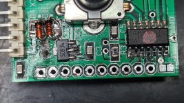
Crap magnified pictures do nok look nice soldering/desoldering smd components 😀
That R1=100r seems to be taking a beating.
J2 (under the board) is connected between pin 2 and 3, just as according to the manual
Tracing the schematics but no luck.
I am sure it is "up in the day" but out of luck here.
Crap magnified pictures do nok look nice soldering/desoldering smd components 😀
That R1=100r seems to be taking a beating.
J2 (under the board) is connected between pin 2 and 3, just as according to the manual
Attachments

Last edited:

- Home
- Source & Line
- Analog Line Level
- MUSES 72320 electronic volume