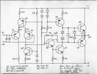
No, it is not my idea, fotios.Tony, this arrangement is an invention of Lineup. In practice, is a thermal compensation of output transistors providing lower 2nd and 3rd harmonic compared to the 2 diodes usually used in this place. Since is first presented, rightfully takes the name LINEUP THERMAL COMPENSATION. I wish you Lineup, a place in the stars of galaxy where they live the wise men of our world (and not a place in Guinness world record book).
Your devoted friend Lineup
Fotis
But I have seen it in forum. In a power output stage.
JENSEN original opamp is using it, too. I think.
Lineup & Fotios Preamplifier
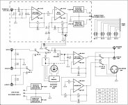
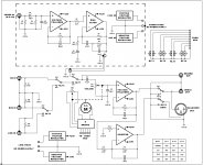
Here is the block diagram of preamplifier (one channel is shown). We have include just 4 inputs. Separate power supply is used for the Phono stage. We use a different way for signal routing thru the input selection Latching relays to the volume pot before the output buffer. The usual way, is the use of a separate relay per each input which of the "common" terminals are tied in a BUS which infected from noise produced from the open contacts of relays. With our way, the contacts of relays are always "loaded". I am only reserved on this: The signal of Phono stage it has to pass thru only one contact before the output buffer and this is OK. But the signal of CD-In it has to pass thru 2 contacts, and the signal of DVD-In and Line-In it has to pass thru 3 contacts. What it bothers me, is that each contact presents stray capacitance and i don't know how much can affect the signal quality. Only the final product will show it thru FFT analysis.
Any advice on this issue, is welcomed!")
Here is the block diagram of preamplifier (one channel is shown). We have include just 4 inputs. Separate power supply is used for the Phono stage. We use a different way for signal routing thru the input selection Latching relays to the volume pot before the output buffer. The usual way, is the use of a separate relay per each input which of the "common" terminals are tied in a BUS which infected from noise produced from the open contacts of relays. With our way, the contacts of relays are always "loaded". I am only reserved on this: The signal of Phono stage it has to pass thru only one contact before the output buffer and this is OK. But the signal of CD-In it has to pass thru 2 contacts, and the signal of DVD-In and Line-In it has to pass thru 3 contacts. What it bothers me, is that each contact presents stray capacitance and i don't know how much can affect the signal quality. Only the final product will show it thru FFT analysis.
Any advice on this issue, is welcomed!
Attachments
Hey, my brothers!
Congratulations on your work.
Keep it up.
I'm glad to you.
But where are you?
Thanks brother Gyuri. I am in my home, the same i believe Lineup. Hard times in Greece, especially in north-eastern Greece where i live
. All of us who are self-employed, as well as private employees, every day we are poorer. Only public and state officials are still in relatively good condition.
Consequently, no reason to be so glad for us. I think that this project will stay on the paper for long time. There is no money left over from food, oil for heating, doctors and medicines and TAXES.
Hi Lineup
I'm interested to know why the unusual selection of MJE 172/182. I know Jensen used them and that simulators will say what models tell them but do you have a reason to select them here in preference to say, MJE243/53 or (as you suggest) BD139/140?
Reason is that i have in my stock only MJE 172/182. No one MJE 243/253 or BD 139/140. MJE 172/182 are not so unusual, they also used in Bryston discrete DOA33. From technical view, BD 139/140 have better bandwidth (according to datasheet of NXP they have ft=160MHz) in the cost of Ic=1,5A, but MJE 243/253 are same with MJE 172/182 except Ic=4A. In simulation, indeed is shown a slight increase of bandwidth with BD 139/140 in output.
Thank you, Fotios. I can well understand that. It seems availability, cost and what we keep for personal stock still varies from region to region around the world.Reason is that i have in my stock only MJE 172/182.
Thank you, Fotios. I can well understand that. It seems availability, cost and what we keep for personal stock still varies from region to region around the world.
Thank you very much Ian for your comprehension, and for your attention on our humble project. You could be sure that if i had BD139/140, will surely have used them. In this instance, it is not an issue of availability. Is just a matter of economic slump. My stock of BD139/140 has been exhausted enough months ago, and i haven't money left over to renew it.
We have designed this project together with Lineup, simply me i did the implementation in practice and - of course - the measurements with real instruments. For this reason i replied instead Lineup.
Fotios
Let's build it!
It seems a pity to see a good idea and some hard work disappear from view.
I would like to construct this design with your PCBs. Would you consider supplying a pair
or enough for others if interested in a small group buy? I realise transactions may not be
simple in all countries but personal accounts with that "PPal" system are quick and convenient for everyone.
@ Ian
Thanks Ian for your interest.
I am positive (the same Lineup) for sharing the whole project. No one objection!
I am already in the process of drawing the PCB of preamplifier. I have ready the plans of the Phono Stage which is a separate unit, optionally included in the preamplifier. I am currently working on the attached block diagram and i will have ready one "home made" PCB at the end of next week. I don't know if it suits in the demands of other people, but there is no problem to we do some variation. Reprogramming of MCU code to suit in each case, is very easy (in 2 hours as much, i can change the code). You should carefully study the block diagram first. Tell me what are you thinking about it.
Attachments
Hi Fotios
For myself, I wish to keep it all very simple. Only the Line Stage (BISBOS) and PSU boards are necessary,
just as in your prototype and assuming the Line Stage board is a stereo pair. That would suit me fine.
Depending on how much you plan to include on the boards and the size and cost, it should not be a problem
to omit these other sections from assembly.
Hi Fotios
For myself, I wish to keep it all very simple. Only the Line Stage (BISBOS) and PSU boards are necessary,
just as in your prototype and assuming the Line Stage board is a stereo pair. That would suit me fine.
Depending on how much you plan to include on the boards and the size and cost, it should not be a problem
to omit these other sections from assembly.
Hi Ian
I am in the process of PCB drawing. The first PCB drawing will be according to the demands of a customer (THANK GOD! i received an order and some money in advance) preamplifier including and a Phono Input. Please, be patient for 1 week to finish the whole preamp (included chassis) which will give a general view of my ideas about a "real world" project. Thanks for your assistance.
Fotios
Main PCB is ready
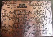
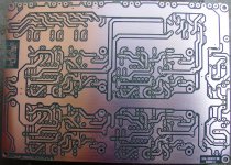
AS i promised, just today i finished the main preamplifier PCB board. It is home made, double sided, 190 X 135 mm. In the two picts, it is drilled and cleaned, ready for the tining of power and gnd tracks.
The first pic is the component side, and the second is the solder side.
Have fun!
AS i promised, just today i finished the main preamplifier PCB board. It is home made, double sided, 190 X 135 mm. In the two picts, it is drilled and cleaned, ready for the tining of power and gnd tracks.
The first pic is the component side, and the second is the solder side.
Have fun!
Attachments
PCB ready for assy
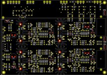
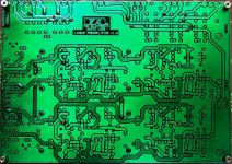
O.K. guys. Here we go! PCB is ready for assembly. There are 27 via holes (0.6mm each one), which have been soldered with spare wire leads from used parts. After this, power and gnd tracks have been tined. Finally, the PCB has been varnished with the nice green PCB encapsulating lacquer of PETERS. Have fun!
O.K. guys. Here we go! PCB is ready for assembly. There are 27 via holes (0.6mm each one), which have been soldered with spare wire leads from used parts. After this, power and gnd tracks have been tined. Finally, the PCB has been varnished with the nice green PCB encapsulating lacquer of PETERS. Have fun!
Attachments
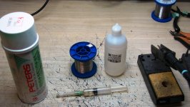
In the picture are presented the tools and the materials that i used. From the left, the first is the green PCB encapsulating lacquer of PETERS. In the middle is the rosin free solder wire (lead free, Sn 96% - Ag 2% - Cu 2%) of ALPHA FRY that i use for the tinning of copper tracks. In the left is the liquid flux of ALPHA FRY that i use for assistance in tinning. I use a syringe for applying the flux. The result is a very clean and effective tinning. Any residue of liquid flux can be removed very easy with common spirit.
Attachments
- Home
- Source & Line
- Analog Line Level
- Preamplifier from Lineup & Fotios for fun