Misc. Ramblings...
Well, I got the second monoblock done, and rebuilt the linestage (tube) so that it can drive a 600ohm load. The sounds is remarkably good, especially considering the 222VA toroid power transformers I'm using as outputs. My magnet wire selection changed, I'll be winding my outputs with 18AWG magnet wire, quadfilar, without taps in the scondaries (no 4:1 capability). Hopefully my wire will come before the weekend, but I expect it'll be early next week...
Susan, you mentioned, breifly, some work you did with an air-core (tri-ax as I recall) transformer, which got me to thinking... We don't need a whole lot of inductance with the turns ratios we're using for the outputs, it'd be interesting to see how your more conventional coils would work with air cores. Do you still have
 wound and not in iron? if so, that oughta be an easy one to test... If it's not convienient for you to test one, I'll do at least a listening test when I get mine wound, I don't have a good setup for doing real measurements, but I'm working on it...
On the subject of changing output transformers, and this is a heads-up for everyone, if you change output transformers, check your bias adjustment, if the DCR of your output transformer primaries are significantly different, it'll have a large effect on your bias...
Peace
Well, I got the second monoblock done, and rebuilt the linestage (tube) so that it can drive a 600ohm load. The sounds is remarkably good, especially considering the 222VA toroid power transformers I'm using as outputs. My magnet wire selection changed, I'll be winding my outputs with 18AWG magnet wire, quadfilar, without taps in the scondaries (no 4:1 capability). Hopefully my wire will come before the weekend, but I expect it'll be early next week...
Susan, you mentioned, breifly, some work you did with an air-core (tri-ax as I recall) transformer, which got me to thinking... We don't need a whole lot of inductance with the turns ratios we're using for the outputs, it'd be interesting to see how your more conventional coils would work with air cores. Do you still have
On the subject of changing output transformers, and this is a heads-up for everyone, if you change output transformers, check your bias adjustment, if the DCR of your output transformer primaries are significantly different, it'll have a large effect on your bias...
Peace
Hi Susan,
The biggest problem for anyone wanting to try your amplifier topology must relate to the transformers.
It is about 30 years since I last wound any for myself and I would no longer look forwards to doing so, but there might well be an inexpensive solution for anyone who is willing/capable of splitting a conventional 'split bobbin' clamp constructed component.
Once the bobbin from say a 6, 12 or 24 volt / 6 or 12 VA ( approx £4 to £5 each ) transformer has been removed from its E-I laminations, the primaries can be torn off and the plastic former cut back until only the standard bifilar wound secondaries are left.
Thus it should be possible to rebuild a transformer using the secondaries from two stock mains transformers to obtain a wide range of input ratios for balanced push-pull Mosfet drive. Also at low input powers it would not matter if the E sections could not be made to fully enmesh.
Such assemblies would obviously not be of audiophile quality, but with a genuinely low impedance input drivng source the resulting reproduction should still be excellent without having to 'gamble' for success via the purchase of a professionally made Sowter component.
The same would apply for 20, 24, 30 and 50 volt 200VA ( approx £22 ) clamp transformers that could be split and cut to construct an output component having the desired turns ratio. Or, use the 'transformer's' secondaries as the 'amplifier's' primary, but unpick the original transformer primary from the bobbin and rewind it with a heavier secondary to match the loudspeaker.
I see that 'Farnell inOne' also stock 15 and 18 volt 330 VA split bobbin clamp transformers too, though at a whopping £59. Its primary could be bifilar rewound as an amplifier primary according to design requirements.
( What made me think of this?
I will shortly assemble, as opposed to wind, my own 'test' input transformer. )
Cheers ............ Graham.
Hi Susan,
I think you will be glad to know that somebody else
design and built SS transformer coupled amplifiers.
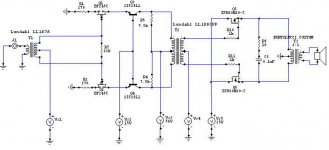
Output transformer is custom BARTOLUCCI DOUBLE C CORE:
nominal power: 100w rms
primery impedance: 32ohms
primery inductance: 510mH
secondary impedance: 4-8-16ohms
primery DC resistence: 1.116ohms
frequency response: 10Hz-100kHz
size: 157x187x172
weight: 20 kG
Input and interstage transformer is Lundahl LL1676
and LL1660/PP.
Power transformer and chokes is BARTOLUCCI custom.
Amplifier is class A-2.5A DC current in primery.
schematic:
I think you will be glad to know that somebody else
design and built SS transformer coupled amplifiers.
Output transformer is custom BARTOLUCCI DOUBLE C CORE:
nominal power: 100w rms
primery impedance: 32ohms
primery inductance: 510mH
secondary impedance: 4-8-16ohms
primery DC resistence: 1.116ohms
frequency response: 10Hz-100kHz
size: 157x187x172
weight: 20 kG
Input and interstage transformer is Lundahl LL1676
and LL1660/PP.
Power transformer and chokes is BARTOLUCCI custom.
Amplifier is class A-2.5A DC current in primery.
schematic:
Attachments
Hi Andrew,
Thank you for your post and interest 🙂
I am pleased that you have found some value in my efforts.
I used exactly the same transformers in the SE version as in the PP so I could do a direct A/B comparison.
Particularly with transformer based amplifiers there is lots of room for experimentation, and trying out gapped cores would be the next logical step. However to keep the bass response one would need to go to a larger lamination size.
Saturation and efficiencys are difficult to judge as there is little that I can find on the Web as to detailed measurements, and everyone seems to measure in different ways as well (I include myself in this).
I am not sure that 0.05% THD at 2 watts is particularly bad for an SE amp? Class A amps by their nature will never win any efficiency awards.
What I do find interesting in the SE configuration is the intermodulation between the harmonics and fundamant. Looking closely I can see this at a lower level in the PP configuration as well.
The bias is necessary to get the "charge" into the inductance. I mostly used 1.0 and 1.5 amps in my testing - as per graphs. If one reduces the bias then the headroom is lowered and one can no longer get a full negative swing to match the positive half of the cycle to the power rail.
A similar 1.5 amp bias for the PP version is divided between the two mosfets, but the heatsink size/area requirement stays the same.
The cores are standard M6 laminations, with a 1:1 head/tail interleave.
Best wishes,
Susan.
Thank you for your post and interest 🙂
Andrew R. said:First of all, I'd like to thank you for sharing this interesting and promising topology with community.
I am pleased that you have found some value in my efforts.
Currently my interest lies in more radical SE approach with o/p coupled with choke or transformer. I couldn't help but notice that your SE testing rig uses transformer without air gap.
I used exactly the same transformers in the SE version as in the PP so I could do a direct A/B comparison.
Particularly with transformer based amplifiers there is lots of room for experimentation, and trying out gapped cores would be the next logical step. However to keep the bass response one would need to go to a larger lamination size.
Perhaps core saturation is a cause of such high distortion and enefficiency (7.5 Vac with almost 2amp quiescent current, IIRC)?
Saturation and efficiencys are difficult to judge as there is little that I can find on the Web as to detailed measurements, and everyone seems to measure in different ways as well (I include myself in this).
I am not sure that 0.05% THD at 2 watts is particularly bad for an SE amp? Class A amps by their nature will never win any efficiency awards.
What I do find interesting in the SE configuration is the intermodulation between the harmonics and fundamant. Looking closely I can see this at a lower level in the PP configuration as well.
The bias is necessary to get the "charge" into the inductance. I mostly used 1.0 and 1.5 amps in my testing - as per graphs. If one reduces the bias then the headroom is lowered and one can no longer get a full negative swing to match the positive half of the cycle to the power rail.
A similar 1.5 amp bias for the PP version is divided between the two mosfets, but the heatsink size/area requirement stays the same.
And if I may ask, what type of core do you use in PP version? I can't remember this from your web pages, although I may be wrong.
The cores are standard M6 laminations, with a 1:1 head/tail interleave.
Best wishes,
Susan.
Re: Misc. Ramblings...
Hi Roscoe,
I am pleased that you are getting good results.
2:1 is much easier to wind than the 4:1 version, although the latter is doable it does require a proper jig and a turns counter. The 2:1 can be done "in the hand".
Unless you have sub 4 ohm impedance speakers you should be fine with 2:1.
The other way to get the 4:1 step down would be to sextuplet-filar wind the bobbin, but even I haven't tried that one 🙂
Yes, I have lots of wound cores not in iron 🙂
My system is in the midst of a rebuild (I am putting the development chassis PSU into a proper case), but I will see what I can do.
I have been away for a few days and now busy catching up, so it is likely that it will be a few days before I can do this.
My expectation is that it will be fine down to about 1 kHz, then performance will drop off rapidly. For bi-amping with an air-core for the HF section this could actually be a benefit.
Inductance can be fine tuned by introducing a partial core, perhaps just using the "I" part of the EI laminations.
Yes. I always turn my bias down to zero and recalibrate whenever I change transformers.
I assume your chassis got a little warm? I hope nothing was damaged.
Best wishes,
Susan.
Hi Roscoe,
Roscoe Primrose said:Well, I got the second monoblock done, and rebuilt the linestage (tube) so that it can drive a 600ohm load. The sounds is remarkably good, especially considering the 222VA toroid power transformers I'm using as outputs.
I am pleased that you are getting good results.
My magnet wire selection changed, I'll be winding my outputs with 18AWG magnet wire, quadfilar, without taps in the scondaries (no 4:1 capability). Hopefully my wire will come before the weekend, but I expect it'll be early next week...
2:1 is much easier to wind than the 4:1 version, although the latter is doable it does require a proper jig and a turns counter. The 2:1 can be done "in the hand".
Unless you have sub 4 ohm impedance speakers you should be fine with 2:1.
The other way to get the 4:1 step down would be to sextuplet-filar wind the bobbin, but even I haven't tried that one 🙂
Susan, you mentioned, breifly, some work you did with an air-core (tri-ax as I recall) transformer, which got me to thinking... We don't need a whole lot of inductance with the turns ratios we're using for the outputs, it'd be interesting to see how your more conventional coils would work with air cores. Do you still have wound and not in iron? if so, that oughta be an easy one to test... If it's not convienient for you to test one, I'll do at least a listening test when I get mine wound, I don't have a good setup for doing real measurements, but I'm working on it...
Yes, I have lots of wound cores not in iron 🙂
My system is in the midst of a rebuild (I am putting the development chassis PSU into a proper case), but I will see what I can do.
I have been away for a few days and now busy catching up, so it is likely that it will be a few days before I can do this.
My expectation is that it will be fine down to about 1 kHz, then performance will drop off rapidly. For bi-amping with an air-core for the HF section this could actually be a benefit.
Inductance can be fine tuned by introducing a partial core, perhaps just using the "I" part of the EI laminations.
On the subject of changing output transformers, and this is a heads-up for everyone, if you change output transformers, check your bias adjustment, if the DCR of your output transformer primaries are significantly different, it'll have a large effect on your bias...
Yes. I always turn my bias down to zero and recalibrate whenever I change transformers.
I assume your chassis got a little warm? I hope nothing was damaged.
Best wishes,
Susan.
Hi rozak,
I saw your new thread last week, and can understand your feelings about sound; the way that a SS NFB amplifier is not only always chasing its own tail, but also unavoidably reacting to its tail being (loudspeaker) pinched: Interface modulated audio (dynamic characterisation) being the result.
That Bartolucci transformer looks properly sized for a good response at low frequency.
Where do they come from, and price ?
I do not intend to purchase, but I am interested in case I eventually take this route, for I too have not yet found a SS amplifier that loud 'rocks' as cleanly as a tube (4xKT88 ultralinear) design.
You say 100 Watt.
A 100W tube amp normally sounds much louder than a 100W solid state design that uses global NFB.
Does your 100W 'follower' output stage sound louder than a NFB solid state, or equally powerful?
Actually Susan, I could ask the same of your 'follower' output design too. Any observations in this regard?
Cheers ............ Graham.
Hi Graham,
Thank you for your post and suggestions 🙂
With particular regard to the input transformers as that part of the circuit is a bit more fussy to get optimum results.
The problem I have found is that many cheepie EI transformers have lower grade steel laminations and they are often welded as well. The varnish impregnation doesn't help in the salvage operation.
The inductance falls off with an increase of air gap, but this would mainly affect the bass response.
This is indeed a point, as the Sowter transformers do represent a considerable investment.
Farnell do do a set of transformer kits, but they are expensive and they do NOT know what type of transformer steel is used for the laminations.
I have been trying to get sorted out to be able to supply M6 laminations, bobbins etc for people who want to try making their own transformers.
It is difficult as there quickly comes a wide range of sizes and options - plus the fact that I have to buy in bulk so I really don't want to have to carry too much that I can't directly use myself (in both senses of the word - a box of 120 size laminations is very heavy to carry up three flights of stairs).
Postage/shipping costs also rapidly escalate as one ends up with packages of the order of 10 kilos (22 lbs). So really only practical for the UK or at a pinch Europe.
Then there is the whole payment side of things. I only have a personal PayPal thingy, and so can't take direct CC payments. If I upgrade to a CC type then I get charged up to 5% per transaction.
So I get to the point where I can't see it being practical. However if people are interested then perhaps email me directly and I will see what can be done.
Ah! 🙂
Is this for the circuit you kindly posted some time back?
Best wishes,
Susan.
Thank you for your post and suggestions 🙂
Graham Maynard said:The biggest problem for anyone wanting to try your amplifier topology must relate to the transformers.
With particular regard to the input transformers as that part of the circuit is a bit more fussy to get optimum results.
It is about 30 years since I last wound any for myself and I would no longer look forwards to doing so, but there might well be an inexpensive solution for anyone who is willing/capable of splitting a conventional 'split bobbin' clamp constructed component.
Once the bobbin from say a 6, 12 or 24 volt / 6 or 12 VA ( approx £4 to £5 each ) transformer has been removed from its E-I laminations, the primaries can be torn off and the plastic former cut back until only the standard bifilar wound secondaries are left.
The problem I have found is that many cheepie EI transformers have lower grade steel laminations and they are often welded as well. The varnish impregnation doesn't help in the salvage operation.
Thus it should be possible to rebuild a transformer using the secondaries from two stock mains transformers to obtain a wide range of input ratios for balanced push-pull Mosfet drive. Also at low input powers it would not matter if the E sections could not be made to fully enmesh.
The inductance falls off with an increase of air gap, but this would mainly affect the bass response.
Such assemblies would obviously not be of audiophile quality, but with a genuinely low impedance input driving source the resulting reproduction should still be excellent without having to 'gamble' for success via the purchase of a professionally made Sowter component.
This is indeed a point, as the Sowter transformers do represent a considerable investment.
The same would apply for 20, 24, 30 and 50 volt 200VA ( approx £22 ) clamp transformers that could be split and cut to construct an output component having the desired turns ratio. Or, use the 'transformer's' secondaries as the 'amplifier's' primary, but unpick the original transformer primary from the bobbin and rewind it with a heavier secondary to match the loudspeaker.
I see that 'Farnell inOne' also stock 15 and 18 volt 330 VA split bobbin clamp transformers too, though at a whopping £59. Its primary could be bifilar rewound as an amplifier primary according to design requirements.
Farnell do do a set of transformer kits, but they are expensive and they do NOT know what type of transformer steel is used for the laminations.
I have been trying to get sorted out to be able to supply M6 laminations, bobbins etc for people who want to try making their own transformers.
It is difficult as there quickly comes a wide range of sizes and options - plus the fact that I have to buy in bulk so I really don't want to have to carry too much that I can't directly use myself (in both senses of the word - a box of 120 size laminations is very heavy to carry up three flights of stairs).
Postage/shipping costs also rapidly escalate as one ends up with packages of the order of 10 kilos (22 lbs). So really only practical for the UK or at a pinch Europe.
Then there is the whole payment side of things. I only have a personal PayPal thingy, and so can't take direct CC payments. If I upgrade to a CC type then I get charged up to 5% per transaction.
So I get to the point where I can't see it being practical. However if people are interested then perhaps email me directly and I will see what can be done.
( What made me think of this?
I will shortly assemble, as opposed to wind, my own 'test' input transformer. )
Ah! 🙂
Is this for the circuit you kindly posted some time back?
Best wishes,
Susan.
Hi Rozak,
Thank you for your post and the images.
It is nice to know that one is not totally alone in the world 🙂
Things sure have moved on in the ten or so years since my original efforts. Even though the Internet did exist at the time it was BG (before Google) and information was scarce and difficult to find even if it was on there somewhere.
BTW Is this a DIY or a commercial amp?
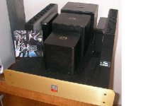
Some beast. Even with being a monoblock I doubt that I could physically lift the amplifier with all that iron.
That 20 kilos is to get 100 Watts at 10 Hz. Sometimes size does matter 🙂
Very nice.
One can but one doesn't have to run at such large bias levels as the push-pull follower configuration does not come out of class A even at higher powers (i.e. there is not as such the AB crossover switching distortion).
I assume there is one output device per heatsink? If so in practice this is not a good idea as the two mosfets should be thermally linked. Even with matching there will be some discrepancy and the mosfets won't otherwise track with temperature.
Any performance figures?
Best wishes,
Susan.
Thank you for your post and the images.
rozak said:I think you will be glad to know that somebody else
design and built SS transformer coupled amplifiers.
It is nice to know that one is not totally alone in the world 🙂
Things sure have moved on in the ten or so years since my original efforts. Even though the Internet did exist at the time it was BG (before Google) and information was scarce and difficult to find even if it was on there somewhere.
BTW Is this a DIY or a commercial amp?
Output transformer is custom BARTOLUCCI DOUBLE C CORE:
nominal power: 100w rms
primery impedance: 32ohms
primery inductance: 510mH
secondary impedance: 4-8-16ohms
primery DC resistence: 1.116ohms
frequency response: 10Hz-100kHz
size: 157x187x172
weight: 20 kG
Some beast. Even with being a monoblock I doubt that I could physically lift the amplifier with all that iron.
That 20 kilos is to get 100 Watts at 10 Hz. Sometimes size does matter 🙂
Input and interstage transformer is Lundahl LL1676
and LL1660/PP.
Power transformer and chokes is BARTOLUCCI custom.
Amplifier is class A-2.5A DC current in primery.
[/B]
Very nice.
One can but one doesn't have to run at such large bias levels as the push-pull follower configuration does not come out of class A even at higher powers (i.e. there is not as such the AB crossover switching distortion).
I assume there is one output device per heatsink? If so in practice this is not a good idea as the two mosfets should be thermally linked. Even with matching there will be some discrepancy and the mosfets won't otherwise track with temperature.
Any performance figures?
Best wishes,
Susan.
Hi Susan,
I'm going to build the corollary - a bipolar version.
Without an output transformer, yet no global feedback either.
Mosfets > voltage drive.
Bipolar > current drive.
News will follow.
Cheers ....... Graham.
I'm going to build the corollary - a bipolar version.
Without an output transformer, yet no global feedback either.
Mosfets > voltage drive.
Bipolar > current drive.
News will follow.
Cheers ....... Graham.
Hi Rozak, Graham,
I didn't appreciate it was your own design Rozak as I missed your thread - a very impressive effort.
My amp does sound loud with only a few watts. The output doesn't sag even with peaks going into the power rail and recovery is instantaneous.
Our standard listening setup is with my original Zeus35 amps in 4:1 step down so the max power is only 12.5 watts or so. 8 ohm nominal impedance speakers are only 86 dB at 1 watt and I never use the amp at max power.
Best wishes,
Susan.
Graham Maynard said:I saw your new thread last week, and can understand your feelings about sound; the way that a SS NFB amplifier is not only always chasing its own tail, but also unavoidably reacting to its tail being (loudspeaker) pinched: Interface modulated audio (dynamic characterisation) being the result.
I didn't appreciate it was your own design Rozak as I missed your thread - a very impressive effort.
You say 100 Watt.
A 100W tube amp normally sounds much louder than a 100W solid state design that uses global NFB.
Does your 100W 'follower' output stage sound louder than a NFB solid state, or equally powerful?
Actually Susan, I could ask the same of your 'follower' output design too. Any observations in this regard?
My amp does sound loud with only a few watts. The output doesn't sag even with peaks going into the power rail and recovery is instantaneous.
Our standard listening setup is with my original Zeus35 amps in 4:1 step down so the max power is only 12.5 watts or so. 8 ohm nominal impedance speakers are only 86 dB at 1 watt and I never use the amp at max power.
Best wishes,
Susan.
Hi Graham,
Interesting 🙂
Look forward to that.
Best wishes,
Susan.
Graham Maynard said:I'm going to build the corollary - a bipolar version.
Without an output transformer, yet no global feedback either.
Mosfets > voltage drive.
Bipolar > current drive.
Interesting 🙂
News will follow.
Look forward to that.
Best wishes,
Susan.
Re: Re: Misc. Ramblings...
I think you'll be surprised. Looking at your inductance vs frquency measurements for the outputs from your website, I wouldn't be surprised if you get down to 100Hz...
No, I've only had the one set of transformers in there so far. I was surprised how high the DCR is on the 225VA toriods (3ohms/side, which gives 1.5Vdc at 0.5A/mosfet), I expect with the quadfilar wound 18AWG the primary DCR will be much lower, I was just thinking ahead...
Yes, but the inductance is much more linear with resect to changing DC offset in the primary. Many of the classic transformer designers (especially Partridge if I recall correctly) recommended/used a small air gap even in PP transformers.
Yes, it can be extremely difficult to find them in small quantities, which is why I ended up re-using transformers I already had...
Peace
Susan-Parker said:Hi Roscoe,
Yes, I have lots of wound cores not in iron 🙂
My expectation is that it will be fine down to about 1 kHz, then performance will drop off rapidly. For bi-amping with an air-core for the HF section this could actually be a benefit.
Inductance can be fine tuned by introducing a partial core, perhaps just using the "I" part of the EI laminations.
I think you'll be surprised. Looking at your inductance vs frquency measurements for the outputs from your website, I wouldn't be surprised if you get down to 100Hz...
Yes. I always turn my bias down to zero and recalibrate whenever I change transformers.
I assume your chassis got a little warm? I hope nothing was damaged.
No, I've only had the one set of transformers in there so far. I was surprised how high the DCR is on the 225VA toriods (3ohms/side, which gives 1.5Vdc at 0.5A/mosfet), I expect with the quadfilar wound 18AWG the primary DCR will be much lower, I was just thinking ahead...
Susan-Parker said:The inductance falls off with an increase of air gap, but this would mainly affect the bass response.
Yes, but the inductance is much more linear with resect to changing DC offset in the primary. Many of the classic transformer designers (especially Partridge if I recall correctly) recommended/used a small air gap even in PP transformers.
I have been trying to get sorted out to be able to supply M6 laminations, bobbins etc for people who want to try making their own transformers.
Yes, it can be extremely difficult to find them in small quantities, which is why I ended up re-using transformers I already had...
Peace
Hi Graham, Susan.
Graham,
Transformer made in Italy by Bartolucci Giuseppe & Co
http://www.audiomarketing.net/bartolucci.htm
Price is 614 euro for 2 pieces.
100W rms is overkill. Amplifier output power is 25W rms-8ohms but sounds loud on few watt, exactly like tube amplifier.
This is the reason why I use this topology.
Sound come not just from follower but from VAS too.
I know. I built preamp with VAS only.
My previous version,no feedback OPTless , is very good amp
but not like this one.
Susan,
This is DIY amplifier.
Maximum current in class A is
BIAS x Turns Ratio.
My follower can give 2.5A x 2 = 5A in class A.
You rigth. Mosfets is not thermally linked but local
DC feedback help. 12 hours of bias measuring show very
good stability and equality.
VAS show 0.02% THD with second harmonic residual.
Follower not measured.
Really, I'm sick from very good measured amp.
Susan, I like your transformer VAS. I'll try it in my next project.
Re: Misc. Ramblings...
Hi Roscoe,
For the air core transformer I think that the distortion will be rising from a decade above 🙁
With 18AWG I make it about 0.7 ohms per winding (although it is difficult to measure accurately at these values). The resistance per foot and the total length used is probably a better way of working it out.
However defining "small" can be quite interesting. With EI laminations there is always a gap of some nominal amount because of the nature of the assembly.
I am going to experiment with some copper shim stock, so I have an accurate and stable thickness.
(When I was designing the flashlamp PSU I found that a post-it note had exactly the right thickness for gapping the flyback transformer, and with the sticky bit they stayed put on the core half whilst I struggled with the clips.)
Hence my efforts to see if I can do something. Shipping costs are really the big stumbling block as it rapidly gets disproportionate to the material costs.
Waste not, want not 🙂
I reuse my laminations and fixtures all the time, so I have several wound bobbins to test out. I do however find it is not usually worth reclaiming the wire as it just gets everywhere and seems to have a hydra's tenacity to trip one up.
Best wishes,
Susan.
Hi Roscoe,
Roscoe Primrose said:I think you'll be surprised. Looking at your inductance vs frquency measurements for the outputs from your website, I wouldn't be surprised if you get down to 100Hz...
For the air core transformer I think that the distortion will be rising from a decade above 🙁
No, I've only had the one set of transformers in there so far. I was surprised how high the DCR is on the 225VA toriods (3ohms/side, which gives 1.5Vdc at 0.5A/mosfet), I expect with the quadfilar wound 18AWG the primary DCR will be much lower, I was just thinking ahead...
With 18AWG I make it about 0.7 ohms per winding (although it is difficult to measure accurately at these values). The resistance per foot and the total length used is probably a better way of working it out.
Yes, but the inductance is much more linear with respect to changing DC offset in the primary. Many of the classic transformer designers (especially Partridge if I recall correctly) recommended/used a small air gap even in PP transformers.
However defining "small" can be quite interesting. With EI laminations there is always a gap of some nominal amount because of the nature of the assembly.
I am going to experiment with some copper shim stock, so I have an accurate and stable thickness.
(When I was designing the flashlamp PSU I found that a post-it note had exactly the right thickness for gapping the flyback transformer, and with the sticky bit they stayed put on the core half whilst I struggled with the clips.)
Yes, it can be extremely difficult to find them in small quantities...
Hence my efforts to see if I can do something. Shipping costs are really the big stumbling block as it rapidly gets disproportionate to the material costs.
... which is why I ended up re-using transformers I already had...
Waste not, want not 🙂
I reuse my laminations and fixtures all the time, so I have several wound bobbins to test out. I do however find it is not usually worth reclaiming the wire as it just gets everywhere and seems to have a hydra's tenacity to trip one up.
Best wishes,
Susan.
Hi Rozak,
Many thanks for the further information.
That would seem to be a very good price indeed, especially for a C core transformer.
🙂
Despite the possible impression from my website I agree with you entirely. There is much more to the quality of the sound than a few numbers.
Thanks 🙂
Best wishes,
Susan.
Many thanks for the further information.
rozak said:Transformer made in Italy by Bartolucci Giuseppe & Co
http://www.audiomarketing.net/bartolucci.htm
Price is 614 euro for 2 pieces.
That would seem to be a very good price indeed, especially for a C core transformer.
This is DIY amplifier.
Maximum current in class A is
BIAS x Turns Ratio.
My follower can give 2.5A x 2 = 5A in class A.
You rigth. Mosfets is not thermally linked but local
DC feedback help. 12 hours of bias measuring show very
good stability and equality.
🙂
VAS show 0.02% THD with second harmonic residual.
Follower not measured.
Really, I'm sick from very good measured amp.
Despite the possible impression from my website I agree with you entirely. There is much more to the quality of the sound than a few numbers.
Susan, I like your transformer VAS. I'll try it in my next project. [/B]
Thanks 🙂
Best wishes,
Susan.
Zeus 6C33C Triode Line Amplifier
Dear All,
A while back we discussed tube based Zeus amplification:
My original 6C33C post...
with my concept schematic:

It took me a while to get it together but here is my breadboard Zeus 6C33C Triode Line Driver 🙂

Some preliminary info (not yet linked from my webpage) at:
http://www.susan-parker.co.uk/zeus-6c33c-line-driver-1.htm
B+ power supply is 65 volts, with 200 mA bias per tube. I am particularly pleased that the circuit works at this low voltage which is well within normal solid state amplifier power supply levels.
Same input and output transformers as my mosfet test version (output tx is quad filar wound with 0.71 mm wire, otherwise the same as the 35W amp output tx):
http://www.susan-parker.co.uk/zeus-line-driver-1.htm
I am still running off bench power supplies. Need to finish a fixed PSU for the B+ supply with a delayed turn on timer.
Best wishes,
Susan.
Dear All,
A while back we discussed tube based Zeus amplification:
My original 6C33C post...
with my concept schematic:
It took me a while to get it together but here is my breadboard Zeus 6C33C Triode Line Driver 🙂
Some preliminary info (not yet linked from my webpage) at:
http://www.susan-parker.co.uk/zeus-6c33c-line-driver-1.htm
B+ power supply is 65 volts, with 200 mA bias per tube. I am particularly pleased that the circuit works at this low voltage which is well within normal solid state amplifier power supply levels.
Same input and output transformers as my mosfet test version (output tx is quad filar wound with 0.71 mm wire, otherwise the same as the 35W amp output tx):
http://www.susan-parker.co.uk/zeus-line-driver-1.htm
I am still running off bench power supplies. Need to finish a fixed PSU for the B+ supply with a delayed turn on timer.
Best wishes,
Susan.
Some thought on the MOSFET Zeus line driver...
The main purpose of the Zeus line driver is to provide a way to drive the 600ohm input of a Zeus power amp, or any other real 600ohm load. However, if you use a high-impeadance input transformer, you get little to no voltage gain out of the line driver as it currently exists...
It occurs to me that for the power amp, we're loading the output stage with a 32ohm load source-to-source (2:1 stepdown, 8ohm speakers). What about using a stepup output transformer? Assuming the same 32ohm s2s load, that's a 4.3:1 stepup. Even is we went with a 2:1 stepup on the output (which should lower the distortion vs the 4.3:1 stepup) that'd be a help, and easier to wind, the (semi)normal quadfilar output transformer with half-way taps on the secondaries could be wired for a 2:1 stepup of you ran it backwards...
Susan, any thoughts?
Peace
Hi Susan,
Yes the bipolar circuit I am working on is similar to the Mosfet one suggested above, but current stabilisation with rail voltage and temperature variation is much less easy to organise.
Nice work with the 6C33Cs.
With your high quality input step-up transformer this gets back to a more idealistic input loading, however the output current is diminished.
Maybe this is where a power bipolar might now be correctly introduced;-
Insert 150 ohms in series with the triode anode.*
Insert 4.7 ohms in series with the triode cathode.*
( * - suggested values off the top of my head.)
Connect power NPN base to cathode.
Connect power NPN emitter to output transformer.
Connect power NPN collector to suitable power ht rail.
Connect 2,200uF bootstrap between NPN emitter and triode anode.
Adjust 4.7 ohms value for suitable quiescent current, say 1 amp.
For very high output power, NPNs may be paralleled with separate low value emitter resistors.
As both anode and cathode would here be made to 'follow' grid potential, maybe the separate low impedance pre-amp might no longer be needed!
Also, if the topology sounds good, then cathode resistor readjustment with the heater voltage reduced by say 10% could make the triode vitually 'everlasting'.
Cheers ........... Graham.
Very interested in Grahams results
I am very interested in Graham's results. From the very moment I saw this thread I began thinking in terms of Bipolar implementation.
For Susan, is it your opinion that the main sonic advantages of your design result from the use of passive voltage amplification, from the special characteristics of the output x-former, or some other combination of factors.
I don't fancy myself an accomplished engineer and I am way out of my league here but permit me to display my ignorance.
I was thinking of an emitter follower input for providing high input impedence that typical home equipment likes (could use 1:1 input x-former if that coupling is preferred) followed by a step up transformer driving another emitter follower for low impedence drive to speakers through a more conventional output transformer or output coupling method of your choice. Would such a topology lose all of the advantages of your design?
mike
- Home
- Amplifiers
- Solid State
- Zero Feedback Impedance Amplifiers