Hi Mike,
I wonder if I might enter my thoughts here.
I don't regard Susan's amplifier, or the one I am trying to make, as being 'passive'.
They are active 'followers'. But unlike NFB amplifiers they are not 'reactive'.
Thus no time delayed products due to loudspeaker back EMF generation are *reactively* countered by a second NFB amplifier input coincidentally operating wrt the input waveform. Yes, the loudspeaker current will still be self back EMF modified, and the follower amplifier's output does become passively loudspeaker current modified, but it does not reactively generate new fractional error voltages that would otherwise arise due to multistage phase change and low biasing.
The original four transistor JLH class-A already behaves very competently in both these regards, but these get so hot when greater power output is required.
An output transformer can have weaknesses at audio frequency extremes and when not operating in pure class-A (which excludes toroidals), but it does have advantages.
Identical per-half devices can be used such that the amplitude differences between halves are not going to generate an underlying alternating voltage error on tonebursts.
Susan's and Rozak's prior constructions utilise an output transformer, and it is only when I simulate realistic values for power rail characteristics, with input, output and bias all established wrt a common ground, that I see the psu does not need to be well regulated, merely power/voltage capable.
Non NFB controlled NPN/PNP complementary push-pull halves amplifiy differently, and thus introduce an underlying error.
An all NPN and output transformerless output stage has the upper half working wrt output and the lower half wrt the negative rail. Only on a simulator can this arrangement be made to work, because low frequency bias shifts arise with current draw when the virtual psu is given real world characteristics.
My conclusion - the output transformer is an essential part of a push-pull 'follower' design, and Susan's simple circuit has for long had much to commend it.
My efforts continue.
Cheers ........... Graham.
Zeus amp & ESL speaker
Hello,
I’m new to this forum and hope I’m not posting in the wrong place.
I've been impressed by the simplicity of the Susan Parker design of the amp and my interest was increased by the mentioning of the suitability to drive ESL speakers.
I am at the moment building a firs prototype of a full-range ESL speaker and winding my own step-up transformers for them, on a second hand winding machine. So here's my question (i apologise if I missed some important issue, but i have no electronics background, being an architect).
1. Can the output transformer and the step-up transformer of the ESL be combined to a single transformer with a lesser step-up ratio so it might be easier to become a wide bandwidth ? If so I suppose the transformer must be completely redesigned ?
2. I understand that the Zeus is a constant current amplifier. Since in theory an ESL that is driven by a constant current has a flat frequency response at large distance, it can might avoid the insertion of (large) resistors between step-up and ESL-stators in order to convert the voltage source into current-source at the cost of efficiency. Is this correct ?
3. Is the layout of the Zeus affected in any way by the reactive load of the ESL ? Is there more/less risk of instability and ringing or can this be controlled in any way without sacrificing the simplicity of the design ?
4. The Zeus is described with several possibilities to connect speakers according to their impedance load. Since the impedance of an ESL is variable (normally starts at 10 Ohm, rising to maybe 150 Ohm and declining to 0.5 Ohm is not unusual), what configuration would be best suited ?
Looking forward for your educating comments.
Edwin
Thanks for the reply Graham. First I just want to clarify that I was only indicating that the voltage amplification was passive in that it was accomplished in the transformers. The active devices being (as I understand it) only acting as unity gain buffers.
I was wondering about the application of these ideas to a single ended topology. I assume that a SE EF stage capacitively coupled to the load would be undesireable but I am curious as to the use of a transformer load to a final SE EF stage. Would such a topology be materialy inferior to the PP orientation (other than power output capability).
Thank you for your patience.
mike
Hi Mike,
For a single ended design to work it would have to run in class-A.
Susan's design is class-AB, but without crossover distortion as it utilises the long gate base of a Mosfet.
Cheers ........... Graham.
For a single ended design to work it would have to run in class-A.
Susan's design is class-AB, but without crossover distortion as it utilises the long gate base of a Mosfet.
Cheers ........... Graham.
Hi Mike,
Maybe I should re-qualify my class-AB wording above.
Susan's and Rozak's output stages first operate fully in class-A for normal listening levels, and the gradual drift into class-AB at higher output powers is observable via the gentle lift in distortion shown in Susan's measurements earlier in this column.
This is not like the sudden bias set shift from 'A to 'AB in a bipolar output stage which causes a sudden increase in distortion.
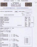
I enquired further about the Bartolucci output transformer and Audiomarketing state that a 5% bias offset can be tolerated, though they did not state what nominally designed bias current is intended. Also that it is a Premium Double C core, has seven split and interleaved winding layers, plus a layered secondary combination.
A 20kg transformer must be good for more than 100W; or does a premium core saturate more sharply ?
20kg is often the checked in baggage limit for budget air travellers these days, so it is little wonder that carriage for two pieces to the UK is 150 Euros. Ouch!
Cheers ........... Graham.
Maybe I should re-qualify my class-AB wording above.
Susan's and Rozak's output stages first operate fully in class-A for normal listening levels, and the gradual drift into class-AB at higher output powers is observable via the gentle lift in distortion shown in Susan's measurements earlier in this column.
This is not like the sudden bias set shift from 'A to 'AB in a bipolar output stage which causes a sudden increase in distortion.
I enquired further about the Bartolucci output transformer and Audiomarketing state that a 5% bias offset can be tolerated, though they did not state what nominally designed bias current is intended. Also that it is a Premium Double C core, has seven split and interleaved winding layers, plus a layered secondary combination.
A 20kg transformer must be good for more than 100W; or does a premium core saturate more sharply ?
20kg is often the checked in baggage limit for budget air travellers these days, so it is little wonder that carriage for two pieces to the UK is 150 Euros. Ouch!
Cheers ........... Graham.
Attachments
Has anyone found a suitable source for transformers in the us to build this amp with? Anyone willing to build them for DIYaudio members in the states?
Suitable transformers from http://www.plitron.com/
1. PAT4152-00
2. PAT 4144-00
From http://www.sowter.co.uk/ for Single Ended
SE14
1. PAT4152-00
2. PAT 4144-00
From http://www.sowter.co.uk/ for Single Ended
SE14
rozak said:
While the PAT4144-00 would be usable, the turns ratio on the PAT4152-00 (7.8:1 on the 8-ohm tap) is really too high unless you have a: very high efficiency speakers, b: a very high stepup ratio on the input transformer (or another way to achieve a very high driving voltage) and c: a relatively high voltage supply in your amp.
Peace
Re: Some thought on the MOSFET Zeus line driver...
Hi Roscoe,
Apologies for the delay in replying.
With my normal line driver configuration I have a 1:4 step up input transformer and a 1:1 line-output transformer, so an overall gain of four. With the 6C33C version the tube higher plate impedance lowers the drive to the line-output transformer and gives a gain of about three times.
More than enough for Hi level sources but I agree may be a bit under for "old" style equipment.
In my testing I see a substantial improvement in the performance (reduction in distortion, lowering of output impedance) going from 2:1 to 4:1 step down for those who don't need lots o' watts. My personal feeling is that the best - impedance match to the speakers / distortion / bias level - trade off is between these ratios.
Moving to 1:1 (choke or transformer) or 1:2 (choke) step up is quite possible, and I specifically designed the Zeus75 output transformer to have to flexibility to be able to be operated in this manner. However the distortion and output impedance will be higher.
If one is running from a lower supply rail, e.g. a 12V automotive system then I would consider using a 1:2 step up.
Having a proper transformer output, rather than a swinging choke, also benefits in that the output stage can survive an inadvertent short circuit (whereas with the swinging inductor the magic smoke escaped).
Time and my own personal requirements (not needing much power for a small listening room) obviously affect the areas that I concentrate on, so input from others is always welcome.
Many thanks.
Best wishes,
Susan.
Hi Roscoe,
Apologies for the delay in replying.
Roscoe Primrose said:The main purpose of the Zeus line driver is to provide a way to drive the 600ohm input of a Zeus power amp, or any other real 600ohm load. However, if you use a high-impedance input transformer, you get little to no voltage gain out of the line driver as it currently exists...
With my normal line driver configuration I have a 1:4 step up input transformer and a 1:1 line-output transformer, so an overall gain of four. With the 6C33C version the tube higher plate impedance lowers the drive to the line-output transformer and gives a gain of about three times.
More than enough for Hi level sources but I agree may be a bit under for "old" style equipment.
It occurs to me that for the power amp, we're loading the output stage with a 32ohm load source-to-source (2:1 stepdown, 8ohm speakers). What about using a stepup output transformer? Assuming the same 32ohm s2s load, that's a 4.3:1 stepup. Even is we went with a 2:1 stepup on the output (which should lower the distortion vs the 4.3:1 stepup) that'd be a help, and easier to wind, the (semi)normal quadfilar output transformer with half-way taps on the secondaries could be wired for a 2:1 stepup of you ran it backwards...
Susan, any thoughts?
In my testing I see a substantial improvement in the performance (reduction in distortion, lowering of output impedance) going from 2:1 to 4:1 step down for those who don't need lots o' watts. My personal feeling is that the best - impedance match to the speakers / distortion / bias level - trade off is between these ratios.
Moving to 1:1 (choke or transformer) or 1:2 (choke) step up is quite possible, and I specifically designed the Zeus75 output transformer to have to flexibility to be able to be operated in this manner. However the distortion and output impedance will be higher.
If one is running from a lower supply rail, e.g. a 12V automotive system then I would consider using a 1:2 step up.
Having a proper transformer output, rather than a swinging choke, also benefits in that the output stage can survive an inadvertent short circuit (whereas with the swinging inductor the magic smoke escaped).
Time and my own personal requirements (not needing much power for a small listening room) obviously affect the areas that I concentrate on, so input from others is always welcome.
Many thanks.
Best wishes,
Susan.
Hi Graham,
Thank you for your post and suggestion.
Thank you. It makes a nice central heating substitute. And that's just one pair for one channel of the line driver. Two pairs plus another two pairs (or quads) for the power amps and the heating will be quite significant.
Tube amps for the colder months, mosfets for the summer 🙂
Certainly looks an interesting hybrid, I will see if I can simulate this. I do have some NPN power devices from my early experiments.
The point with the pure tube triode implementation is to show that the Zeus follower topology is perfectly usable with vacuum devices.
Also I am seeing if I can implement the audio path entirely with 1920's style technology. The 6C33C has an indirectly heated cathode, but the same circuit can be accomplished with pairs of directly heated tubes such as the 300B with the heaters in series.

Next is to try out a 6C33C power output stage with higher B+ of about 140 volts and something like a 10:1 step down output transformer.
Best wishes,
Susan.
Thank you for your post and suggestion.
Graham Maynard said:...
Nice work with the 6C33Cs.
Thank you. It makes a nice central heating substitute. And that's just one pair for one channel of the line driver. Two pairs plus another two pairs (or quads) for the power amps and the heating will be quite significant.
Tube amps for the colder months, mosfets for the summer 🙂
With your high quality input step-up transformer this gets back to a more idealistic input loading, however the output current is diminished.
Maybe this is where a power bipolar might now be correctly introduced...
... snip ...
Certainly looks an interesting hybrid, I will see if I can simulate this. I do have some NPN power devices from my early experiments.
The point with the pure tube triode implementation is to show that the Zeus follower topology is perfectly usable with vacuum devices.
Also I am seeing if I can implement the audio path entirely with 1920's style technology. The 6C33C has an indirectly heated cathode, but the same circuit can be accomplished with pairs of directly heated tubes such as the 300B with the heaters in series.
Next is to try out a 6C33C power output stage with higher B+ of about 140 volts and something like a 10:1 step down output transformer.
Best wishes,
Susan.
Re: Very interested in Grahams results
Hi Mike,
Thank you for your post and interest 🙂
Yes, passive voltage amplification with followers that have a gain under unity, without global negative feedback, and single rail operation. No capacitors in the signal path. Very simple "direct connect" topology.
Also can be built simply, often with bits that are to hand.
Ignorance is only knowledge that one has not yet acquired. When I started out on this design I didn't have much of a clue as to what I was doing, just a "feeling" about going back to basics and trying to keep things very very simple.
I have lived and breathed this amp now for over a decade, and even so there are still things that I am working out.
So please ask questions 🙂
I didn't have as much success with bipolar devices as I did with mosfets when I did my original work. But that was over ten years ago and I must admit I can't remember in detail the particular reasons.
Time permitting I will have another look as I have some power NPNs lurking in a box somewhere.
Transformer coupling is how I do things, but there is no reason why you shouldn't experiment with other variations.
When I show the "simplified" line drawing schematics, like in my previous post about the 6C33C line driver, these are actually the real circuit. Obviously I have to add power supplies and biasing to get a working amplifier, but if you see 5 components in the audio path for a amplifier stage then there are actually only 5 components used.
The use of a single voltage rail is a huge advantage, and with the output transformer the amp gets to swing near double the supply volts.
Hope this helps 🙂
Best wishes,
Susan.
Hi Mike,
Thank you for your post and interest 🙂
mashaffer said:... From the very moment I saw this thread I began thinking in terms of Bipolar implementation.
For Susan, is it your opinion that the main sonic advantages of your design result from the use of passive voltage amplification, from the special characteristics of the output x-former, or some other combination of factors.
Yes, passive voltage amplification with followers that have a gain under unity, without global negative feedback, and single rail operation. No capacitors in the signal path. Very simple "direct connect" topology.
Also can be built simply, often with bits that are to hand.
I don't fancy myself an accomplished engineer and I am way out of my league here but permit me to display my ignorance.
Ignorance is only knowledge that one has not yet acquired. When I started out on this design I didn't have much of a clue as to what I was doing, just a "feeling" about going back to basics and trying to keep things very very simple.
I have lived and breathed this amp now for over a decade, and even so there are still things that I am working out.
So please ask questions 🙂
I was thinking of an emitter follower input for providing high input impedance that typical home equipment likes (could use 1:1 input x-former if that coupling is preferred) followed by a step up transformer driving another emitter follower for low impedance drive to speakers through a more conventional output transformer or output coupling method of your choice. Would such a topology lose all of the advantages of your design?
I didn't have as much success with bipolar devices as I did with mosfets when I did my original work. But that was over ten years ago and I must admit I can't remember in detail the particular reasons.
Time permitting I will have another look as I have some power NPNs lurking in a box somewhere.
Transformer coupling is how I do things, but there is no reason why you shouldn't experiment with other variations.
When I show the "simplified" line drawing schematics, like in my previous post about the 6C33C line driver, these are actually the real circuit. Obviously I have to add power supplies and biasing to get a working amplifier, but if you see 5 components in the audio path for a amplifier stage then there are actually only 5 components used.
The use of a single voltage rail is a huge advantage, and with the output transformer the amp gets to swing near double the supply volts.
Hope this helps 🙂
Best wishes,
Susan.
Re: Re: Some thought on the MOSFET Zeus line driver...
I was talking more about a stepup for the line driver output, which could be handy if you need to use a higher impeadance 1:1 or so input transformer to match the rest of your system. It's not the transformer stepup/stepdown ratio that determines the distortion in the output stage, it's the reflected source-to-source impeadance. What I was trying to say is that in the line driver application we could use a 1:4 stepup into a 600ohm load and still have the same reflected impeadance as the power amp with a 2:1 stepdown into an 8ohm load.
Peace
Susan-Parker said:Hi Roscoe,
In my testing I see a substantial improvement in the performance (reduction in distortion, lowering of output impedance) going from 2:1 to 4:1 step down for those who don't need lots o' watts. My personal feeling is that the best - impedance match to the speakers / distortion / bias level - trade off is between these ratios.
Moving to 1:1 (choke or transformer) or 1:2 (choke) step up is quite possible, and I specifically designed the Zeus75 output transformer to have to flexibility to be able to be operated in this manner. However the distortion and output impedance will be higher.
I was talking more about a stepup for the line driver output, which could be handy if you need to use a higher impeadance 1:1 or so input transformer to match the rest of your system. It's not the transformer stepup/stepdown ratio that determines the distortion in the output stage, it's the reflected source-to-source impeadance. What I was trying to say is that in the line driver application we could use a 1:4 stepup into a 600ohm load and still have the same reflected impeadance as the power amp with a 2:1 stepdown into an 8ohm load.
Peace
Re: Some thought on the MOSFET Zeus line driver...
Hi Roscoe,
Ah! Okay, understood.
Yes, with the mosfet line driver this is worth looking at.
My headspace is currently in 6C33C triode mode...
Um, thinking about how the transformer can be made.
I happen to have just wound a gaped 120 size transformer with 0.71 mm wire, which could be configured for a 1:2 step up (it does 4:1 step down).
That should work, as there are 120 turns per side per wire.
Multi-filar windings get a bit more complicated beyond these ratios.
Thanks for the input 🙂
Best wishes,
Susan.
Hi Roscoe,
Roscoe Primrose said:I was talking more about a stepup for the line driver output, which could be handy if you need to use a higher impeadance 1:1 or so input transformer to match the rest of your system. It's not the transformer stepup/stepdown ratio that determines the distortion in the output stage, it's the reflected source-to-source impeadance. What I was trying to say is that in the line driver application we could use a 1:4 stepup into a 600ohm load and still have the same reflected impeadance as the power amp with a 2:1 stepdown into an 8ohm load.
Ah! Okay, understood.
Yes, with the mosfet line driver this is worth looking at.
My headspace is currently in 6C33C triode mode...
Um, thinking about how the transformer can be made.
I happen to have just wound a gaped 120 size transformer with 0.71 mm wire, which could be configured for a 1:2 step up (it does 4:1 step down).
That should work, as there are 120 turns per side per wire.
Multi-filar windings get a bit more complicated beyond these ratios.
Thanks for the input 🙂
Best wishes,
Susan.
Re: Re: Some thought on the MOSFET Zeus line driver...
I didn't say it would be easy 😉
The Lundahl LL1674 might be a good choice here, 1+1:4+4, 95USD/each, good for over 20VRMS output, more than I expect I'll ever need for a line driver!
I just figured out a possible use for the 120+120:18+18 toroids I was originally using for outputs, I've got a pair of Philips 8" full-rangers that are 600ohm, run those toriods backwards, and I might have something...
What, not ready to wind the decafilar version quite yet 😉
Peace
Susan-Parker said:Um, thinking about how the transformer can be made.
I didn't say it would be easy 😉
The Lundahl LL1674 might be a good choice here, 1+1:4+4, 95USD/each, good for over 20VRMS output, more than I expect I'll ever need for a line driver!
I happen to have just wound a gaped 120 size transformer with 0.71 mm wire, which could be configured for a 1:2 step up (it does 4:1 step down).
I just figured out a possible use for the 120+120:18+18 toroids I was originally using for outputs, I've got a pair of Philips 8" full-rangers that are 600ohm, run those toriods backwards, and I might have something...
Multi-filar windings get a bit more complicated beyond these ratios.
What, not ready to wind the decafilar version quite yet 😉
Peace
Hi All,
Way back at the beginning of this thread I stated that I did not like output transformers.
My reason being that I have heard the individual effects upon reproduction due to insufficient winding inductance, winding capacitance, copper losses, and poor interleaving technique, which NFB cannot fully counter in a tube amplifier design without introducing more (phase shift related) problems.
In another thread Lumanauw is discussing passband phase change at audio frequencies, which is something I have for long now attempted to minimise in directly coupled NFB amplifier circuitry.
Rozak has above informed us of his choice for the Bartolucci 6060 transformer. This has a primary inductance circa 0.5 Henry which equates to a 32 ohm impedance at 10Hz, and is the same as the transformed load impedance.
Bartolucci quote a -3dB response of 10Hz to 100kHz. Correct.
The phase shift at a -3dB turnover is demonstrable as being 45 degrees, and I know for sure that I would be able to hear that after my experiences with a variable bass phase shifter where reproduction sounds as if correct only when the phase is true down to (and below for the likes of kick drums and auditorium ambience) the lower limit of human hearing.
So how can Rozak be satisfied ?
Also, how come Susan was amazed at how low in frequency her amplifier reproduced when the 'output transformer' was no more than an air cored 100 meter roll of cable.
Susan will recall the inductance figure better than I can ( 4mH? and was it screened twin? )
The reason only came to me this afternoon when thinking about my own version, and it is down to the driving impedance of the output stage as compared to those of the common source/emitter ouput stage requirements normally envisioned.
Assuming as little as an easy 20dB damping factor from these 'follower' designs, the Bartolucci output transformer will achieve a -3dB turnover of *1Hz*, with the phase shift at 20Hz being an inaudible 2.6 degrees for low level listening. Audio type Mosfets actually manage circa 30dB of damping, whereupon the associated figures of -3dB at approx 0.35Hz and just one degree of phase shift at 20Hz could be realised !!!!! Clearly the psu will be the limiting factor when there is low frequency input.
Similar improvements will arise at the higher frequency end, and boy do I feel dumb for not realising all this before.
So Susan, a well made output transformer does not render your's and Rozak's designs inferior, in fact with their isolation capabilities, allowance of common grounding and unfussiness in relation to PSUs - their utilisation within a 'follower' output stage does actually lead to improved reproduction.
Thanks for keeping going long enough for me to wake up !!!!!
Rozak, your system might go so low that the bass cone could 'breathe' due to unavoidable analogue-digital-analogue conversion techniques.
Cheers ........... Graham.
Graham Maynard said:
Rozak, your system might go so low that the bass cone could 'breathe' due to unavoidable analogue-digital-analogue conversion techniques.
Cheers ........... Graham.
Absolutely right. My furniture agree with you also.
Re: Zeus amp & ESL speaker
Hi Edwin,
Once again my apologies for the delay in replying, this week has somehow been very busy for me.
Right place 🙂
🙂
Yes, you can use a single transformer.
I am a bit more hazy here as I don't have much experience with electrostatics. My understanding is that one uses a large value resistor to minimize the current to the membrane film power supply, and to avoid the prospect of death if one accidently touched it.
I can't say for certain as I haven't tried this configuration, but I do not see any immediate problems.
If you bifilar wind the primaries then you can use the transformer in PP directly from the mosfets.
If for some reason this isn't working as you expected you can always drive the transformer from a conventional amplifier (backup plan "B").
These impedances are only at the other end of the transformer, not for the electrostatic bit. The impedance the amplifier sees will be dependent on the step up ratio (and the frequency if these is a frequency dependent part).
My LCR meter only does 1 kHz or 120 Hz so for quick tests I am limited to those two frequencies.
A few questions:
What power supply voltage are you using for the amp?
What power supply voltage are you using for the speaker (2Kv, 3Kv,...)?
What PP voltage across the plates are you aiming for?
Are you using a dual chamber bobbin?
How many layer sections are you looking at?
What step up ratio are you after (I assume 1:60 max)?
===
With your own coil winding machine the world's your oyster 🙂
If you are still in experimental mode (or others that might be thinking about this application) one could try a stack of mains toroids to construct a test output transformer.
For example eight off 120 VA 120 + 120 : 12 + 12 mains transformers be could wired with the 12 volt windings in series-parallel (2+2) and the 120 windings in series to give 24 + 24 : 960 + 960 i.e. a 1:40 step up ( I assume here something around 30 volts for the Zeus power supply rail).
This gives in effect a 24 sectioned 960 VA transformer.
Use 4 for one side, 4 for the other to limit the peak volts across the normal mains windings of each transformer i.e. don't interleave the HV secondaries (just interleave the LV primaries).
One should check the isolation specifications between the primaries and the secondaries and for general main toroids I suspect the limit is probably a stack of eight max.
I don't know what the HF response is going to be like but I have been pleasantly surprised by some of the mains toroid's bandwidths.
Best wishes,
Susan.
Hi Edwin,
Once again my apologies for the delay in replying, this week has somehow been very busy for me.
EdwinR3 said:I’m new to this forum and hope I’m not posting in the wrong place.
Right place 🙂
I've been impressed by the simplicity of the Susan Parker design of the amp and my interest was increased by the mentioning of the suitability to drive ESL speakers.
I am at the moment building a firs prototype of a full-range ESL speaker and winding my own step-up transformers for them, on a second hand winding machine. So here's my question (i apologise if I missed some important issue, but i have no electronics background, being an architect).
🙂
1. Can the output transformer and the step-up transformer of the ESL be combined to a single transformer with a lesser step-up ratio so it might be easier to become a wide bandwidth ? If so I suppose the transformer must be completely redesigned ?
Yes, you can use a single transformer.
2. I understand that the Zeus is a constant current amplifier. Since in theory an ESL that is driven by a constant current has a flat frequency response at large distance, it can might avoid the insertion of (large) resistors between step-up and ESL-stators in order to convert the voltage source into current-source at the cost of efficiency. Is this correct ?
I am a bit more hazy here as I don't have much experience with electrostatics. My understanding is that one uses a large value resistor to minimize the current to the membrane film power supply, and to avoid the prospect of death if one accidently touched it.
3. Is the layout of the Zeus affected in any way by the reactive load of the ESL ? Is there more/less risk of instability and ringing or can this be controlled in any way without sacrificing the simplicity of the design ?
I can't say for certain as I haven't tried this configuration, but I do not see any immediate problems.
If you bifilar wind the primaries then you can use the transformer in PP directly from the mosfets.
If for some reason this isn't working as you expected you can always drive the transformer from a conventional amplifier (backup plan "B").
4. The Zeus is described with several possibilities to connect speakers according to their impedance load. Since the impedance of an ESL is variable (normally starts at 10 Ohm, rising to maybe 150 Ohm and declining to 0.5 Ohm is not unusual), what configuration would be best suited ?
These impedances are only at the other end of the transformer, not for the electrostatic bit. The impedance the amplifier sees will be dependent on the step up ratio (and the frequency if these is a frequency dependent part).
My LCR meter only does 1 kHz or 120 Hz so for quick tests I am limited to those two frequencies.
A few questions:
What power supply voltage are you using for the amp?
What power supply voltage are you using for the speaker (2Kv, 3Kv,...)?
What PP voltage across the plates are you aiming for?
Are you using a dual chamber bobbin?
How many layer sections are you looking at?
What step up ratio are you after (I assume 1:60 max)?
===
With your own coil winding machine the world's your oyster 🙂
If you are still in experimental mode (or others that might be thinking about this application) one could try a stack of mains toroids to construct a test output transformer.
For example eight off 120 VA 120 + 120 : 12 + 12 mains transformers be could wired with the 12 volt windings in series-parallel (2+2) and the 120 windings in series to give 24 + 24 : 960 + 960 i.e. a 1:40 step up ( I assume here something around 30 volts for the Zeus power supply rail).
This gives in effect a 24 sectioned 960 VA transformer.
Use 4 for one side, 4 for the other to limit the peak volts across the normal mains windings of each transformer i.e. don't interleave the HV secondaries (just interleave the LV primaries).
One should check the isolation specifications between the primaries and the secondaries and for general main toroids I suspect the limit is probably a stack of eight max.
I don't know what the HF response is going to be like but I have been pleasantly surprised by some of the mains toroid's bandwidths.
Best wishes,
Susan.
Hi Mike,
Both line amp and power amp can be SE instead of PP.

See middle section of line driver page:
http://www.susan-parker.co.uk/zeus-line-driver-1.htm
And for the power amp:
http://www.susan-parker.co.uk/zeus-se-amp.htm
Note the use of the same transformers as with the PP circuits, without any gaps. Improvement may be possible with gapped (and therefor being larger in physical size) transformers. I will have to try this.
Note also the intermodualtion effect between the fundamant and it's harmonics. Looking carefully at my PP tests I see that this effect also occurs in PP circuits, but at a much lower level in the mosfet version and is not really apparent unless on is specifically looking for them.
In the 6C33C triode PP tests these intermodulation effects are a lot higher, which probably corresponds to the higher driving impedance.
http://www.susan-parker.co.uk/zeus-6c33c-line-driver-1.htm
With the 6C33C triode PP circuit there is no great difference in the distortion levels or pattern of harmonics seen in the FFTs with a gaped core transformer, with the one exception that these intermodulation products are a decade lower.
I wonder if these intermodulation products are in part what distinguishes "tube sound" from solid state sound?
Best wishes,
Susan.
mashaffer said:I was wondering about the application of these ideas to a single ended topology. I assume that a SE EF stage capacitively coupled to the load would be undesireable but I am curious as to the use of a transformer load to a final SE EF stage. Would such a topology be materialy inferior to the PP orientation (other than power output capability).
Both line amp and power amp can be SE instead of PP.
See middle section of line driver page:
http://www.susan-parker.co.uk/zeus-line-driver-1.htm
And for the power amp:
http://www.susan-parker.co.uk/zeus-se-amp.htm
Note the use of the same transformers as with the PP circuits, without any gaps. Improvement may be possible with gapped (and therefor being larger in physical size) transformers. I will have to try this.
Note also the intermodualtion effect between the fundamant and it's harmonics. Looking carefully at my PP tests I see that this effect also occurs in PP circuits, but at a much lower level in the mosfet version and is not really apparent unless on is specifically looking for them.
In the 6C33C triode PP tests these intermodulation effects are a lot higher, which probably corresponds to the higher driving impedance.
http://www.susan-parker.co.uk/zeus-6c33c-line-driver-1.htm
With the 6C33C triode PP circuit there is no great difference in the distortion levels or pattern of harmonics seen in the FFTs with a gaped core transformer, with the one exception that these intermodulation products are a decade lower.
I wonder if these intermodulation products are in part what distinguishes "tube sound" from solid state sound?
Best wishes,
Susan.
Hi Graham,
Thank you for your posts.
I am not sure what they consider to be a premium core but I was looking at microcrystaline split C cores from MK Magnetics in the USA.
Looking back at my correspondence I wrote:
Assuming I have my figures correct...
M6 has a saturation flux density of about 20,000 Gauss
Nanocrystalline has a saturation flux density of 12,300 Gauss.
So I would need to increase the core size from 3 sq in to 4.88 sq in. This translates to the next size bobbin which is an imperial size type 638 x 2.5", with a bit over 5.25 sq in cross section. However checking I see that 2-5/8" is available from several places, but 2-1/2" only from one. So I guess an extra bit of depth here.
2-1/8" EI Laminations have two apertures of 3-3/16" by 1-1/16" with 1-1/16" limb widths.
So each C core is 1-1/16" thick and should have a finished width of just under 2-5/8", see pdf link below.
Imperial 683 bobbin http://www.miles-platts.com/pdf/l05110.pdf
N.B. The bobbin center hole is specified as being 2.625" wide from the other supplier.
After my initial inquiry it went quite, perhaps my prospective order (test out for one pair of transformers) wasn't big enough?
I work on 20 Hz minimum at full power (I believe in having a separate speaker/amp for low bass). For 10Hz one doubles the core size (and weight). Then with the premium material increase the size all round for the lower unit cross section core saturation. Then add a full steel box. Easy to see how the weight adds up.
This is a big problem. A pair of Zeus 75 output transformers in a box weighs about 10 kg. Overseas shipping from the UK can be up to UKP 100 (or more). I can make to sell these transformers starting at UKP 95 each (plus packaging costs and VAT (17.5%) for EU countries), but shipping is just so horrendous I can't see it being viable.
Sowter, as they ship large amounts, will undoubtedly have a contract with a shipping agent and I imagine should have at least a 1/4 to 1/3 off the standard one off shipping charges that I would pay.
Best wishes,
Susan.
Thank you for your posts.
Graham Maynard said:... snip... Also that it is a Premium Double C core, has seven split and interleaved winding layers, plus a layered secondary combination.
A 20kg transformer must be good for more than 100W; or does a premium core saturate more sharply ?
I am not sure what they consider to be a premium core but I was looking at microcrystaline split C cores from MK Magnetics in the USA.
Looking back at my correspondence I wrote:
Assuming I have my figures correct...
M6 has a saturation flux density of about 20,000 Gauss
Nanocrystalline has a saturation flux density of 12,300 Gauss.
So I would need to increase the core size from 3 sq in to 4.88 sq in. This translates to the next size bobbin which is an imperial size type 638 x 2.5", with a bit over 5.25 sq in cross section. However checking I see that 2-5/8" is available from several places, but 2-1/2" only from one. So I guess an extra bit of depth here.
2-1/8" EI Laminations have two apertures of 3-3/16" by 1-1/16" with 1-1/16" limb widths.
So each C core is 1-1/16" thick and should have a finished width of just under 2-5/8", see pdf link below.
Imperial 683 bobbin http://www.miles-platts.com/pdf/l05110.pdf
N.B. The bobbin center hole is specified as being 2.625" wide from the other supplier.
After my initial inquiry it went quite, perhaps my prospective order (test out for one pair of transformers) wasn't big enough?
20kg is often the checked in baggage limit for budget air travellers these days, so it is little wonder that carriage for two pieces to the UK is 150 Euros. Ouch!
I work on 20 Hz minimum at full power (I believe in having a separate speaker/amp for low bass). For 10Hz one doubles the core size (and weight). Then with the premium material increase the size all round for the lower unit cross section core saturation. Then add a full steel box. Easy to see how the weight adds up.
This is a big problem. A pair of Zeus 75 output transformers in a box weighs about 10 kg. Overseas shipping from the UK can be up to UKP 100 (or more). I can make to sell these transformers starting at UKP 95 each (plus packaging costs and VAT (17.5%) for EU countries), but shipping is just so horrendous I can't see it being viable.
Sowter, as they ship large amounts, will undoubtedly have a contract with a shipping agent and I imagine should have at least a 1/4 to 1/3 off the standard one off shipping charges that I would pay.
Best wishes,
Susan.
Re: Re: Re: Some thought on the MOSFET Zeus line driver...
Hi Roscoe,
The problem is that the two primaries are on separate bobbin sections and for the Zeus PP they won't couple properly.
Looking at the Lundahl data sheets type LL1680 has the configuration one is looking for. Looking at the 1+1+1+1 side one has to take one winding from each side for each arm of the Zeus primary i.e. 1-3 + 8-7 one side, and 2-4 + 7-5 the other, 7 and 2 joined as the center tap to ground..
These transformers are quite small, and on spec have a disappointing frequency response. May go higher with the lower impedance drive?
Probably can't take the bias current either.
Interesting...
Don't think I haven't considered that 🙂
The problem is that the multi-filar construction really only works well for unity or small step up/down ratios. Beyond 4:1 through 1:2 the optimum wire diameters start becoming sufficiently different that the advantages of multi-filar no longer work in one's favor.
Additionally winding capacitance starts to figure, so one goes over to a conventional layered construction, still using bi-filar windings for the primaries of course.
There are other ways of skinning this problem though, and I hope to have some results to show in due course.
And maybe I am just being too fussy about neat and ordered layers and allowing myself to be blocked by conventional wisdom. Wire gauge would have to stay at 0.71 mm else the current rating of the wire is getting on the low side and one would not be able to set the mosfet bias high enough. On a 120 size double chamber bobbin (at a guess) one would get about 50 turns per wire per side.
Best wishes,
Susan.
Hi Roscoe,
Roscoe Primrose said:The Lundahl LL1674 might be a good choice here, 1+1:4+4, 95USD/each, good for over 20VRMS output, more than I expect I'll ever need for a line driver!
The problem is that the two primaries are on separate bobbin sections and for the Zeus PP they won't couple properly.
Looking at the Lundahl data sheets type LL1680 has the configuration one is looking for. Looking at the 1+1+1+1 side one has to take one winding from each side for each arm of the Zeus primary i.e. 1-3 + 8-7 one side, and 2-4 + 7-5 the other, 7 and 2 joined as the center tap to ground..
These transformers are quite small, and on spec have a disappointing frequency response. May go higher with the lower impedance drive?
Probably can't take the bias current either.
I just figured out a possible use for the 120+120:18+18 toroids I was originally using for outputs, I've got a pair of Philips 8" full-rangers that are 600ohm, run those toriods backwards, and I might have something...
Interesting...
What, not ready to wind the decafilar version quite yet.
Don't think I haven't considered that 🙂
The problem is that the multi-filar construction really only works well for unity or small step up/down ratios. Beyond 4:1 through 1:2 the optimum wire diameters start becoming sufficiently different that the advantages of multi-filar no longer work in one's favor.
Additionally winding capacitance starts to figure, so one goes over to a conventional layered construction, still using bi-filar windings for the primaries of course.
There are other ways of skinning this problem though, and I hope to have some results to show in due course.
And maybe I am just being too fussy about neat and ordered layers and allowing myself to be blocked by conventional wisdom. Wire gauge would have to stay at 0.71 mm else the current rating of the wire is getting on the low side and one would not be able to set the mosfet bias high enough. On a 120 size double chamber bobbin (at a guess) one would get about 50 turns per wire per side.
Best wishes,
Susan.
- Home
- Amplifiers
- Solid State
- Zero Feedback Impedance Amplifiers