which to choose Zeus or circlotrone?
Transforming the class A Zeus to class B circlotron I got the following result.
Can someone of knowledge for both circuits advise me which to choose?
After doubts expressed by pieter t ,I ordered the following
600:10K audio cattle imports permalloy audio transformer audio balance unbalanced conversion-in Transformers from Home Improvement on Aliexpress.com | Alibaba Group
Attachments

Hi Apelizzo!
Could you tell me more detail about your input transformer?
Greets:
Tyimo
Hi Tyimo,
Sorry for this late reply.
I posted the details in page 160.
What else do you need to know about the input transformer?
Hi Apelizzo!
Thanks! In the meantime, I remembered that you showed it already.🙂
What iron did you use?
Thanks! In the meantime, I remembered that you showed it already.🙂
What iron did you use?
Hi Apelizzo!
Thanks! In the meantime, I remembered that you showed it already.🙂
What iron did you use?
Hi, I have used M6 only
would the H3 get lower if instead of using an input transformer, we use a balanced source to feed each mosfet?
gates directly biased and signal fed with capacitor
gates directly biased and signal fed with capacitor
Transforming the class A Zeus to class B circlotron I got the following result.
Can someone of knowledge for both circuits advise me which to choose?
After doubts expressed by pieter t ,I ordered the following
600:10K audio cattle imports permalloy audio transformer audio balance unbalanced conversion-in Transformers from Home Improvement on Aliexpress.com | Alibaba Group
Hello,
How is the Circlotron design progressing? I am interested in this.
As far as I understand I can see you are using a 1:4 step up transformer. You need at least 12K input source impedance to drive IRFP150 to ~22KHz -3dB at the gates. In source follower Ciss 2800pF Crss 280pF and S 13 give Gate input capacitance of about 616pF.
For 50Khz you would need 5K input at the gates. As you step up four times 5K/16= 312 Ohms
Last edited:
I think I’d like to build one similar to Susan’s original implementation. Hammond makes a 12w 600:8/4 transformer that might work for smaller version (compared to the original Zeus). But is it strictly necessary that the primary be center tapped?
"Classic" 600 Ohm (119DA Series) - Hammond Mfg.
Brian
Edit: Answering my own question, perhaps. I presume without a center tap the DC current isn’t balanced and cancelled through the primary.
"Classic" 600 Ohm (119DA Series) - Hammond Mfg.
Brian
Edit: Answering my own question, perhaps. I presume without a center tap the DC current isn’t balanced and cancelled through the primary.
Last edited:
there are several ways to implement this, one is by center tapped traffo and the other is by using ccs and then a traffo...
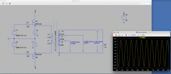
Something like this?
Nice simulation.
The point about the centre ground tap is that the two primary halves are coupled and so the one going positive couple to the other which goes negative.
Without this coupling, the negative side of the input transformer secondary will attempt to drive the gate negative, and thus may drive the gate outside the input V limit; which is followed by a bang, or clamp which just gives distortion.
Overdriving the gate input will result in pain and misery, as I can personally attest.
I think I’d like to build one similar to Susan’s original implementation. Hammond makes a 12w 600:8/4 transformer that might work for smaller version (compared to the original Zeus). But is it strictly necessary that the primary be center tapped?
"Classic" 600 Ohm (119DA Series) - Hammond Mfg.
Brian
Edit: Answering my own question, perhaps. I presume without a centre tap the DC current isn’t balanced and cancelled through the primary.
Brian, you could use this transformer in a low-power single-ended configuration but you would have to dissemble the interleaved laminations and put them back together as a separated E and I with a gap (about 1/2 to 1 mm). If the transformer is covered in a lacquer coating (probably) this would be a bit of a job and might well involve payments to the swear-jar.
The line-driver (SE) and output (SE or PP) transformers use relatively few turns of quite thick magnet wire, so it is quite possible to hand wind them. Literally holding the bobbin in one's hand and winding on the wire. This is how I built my first transformers. N.B. your wrists will likely ache a bit by the end of the exercise 🙂
Susan,
Long time no hear.
Hope all is well with you.
Best regards,
Patrick
Hi Patrick,
Thanks. My partner and I are both well, although a bit stir-crazy after being in lockdown since the middle of March. I will start going back to work 1 or 2 days a week from the 1st July, in the Department of Physics at Imperial College.
Hope you and yours (as with everyone else reading this) are well and safe.
How are your audio projects going?
Best wishes,
Susan.
zeus amp
Dear Susan I cannot see the difference between your amp and a valve pp output. so how is it novel? yours truly ampman.
Dear Susan I cannot see the difference between your amp and a valve pp output. so how is it novel? yours truly ampman.
Push-pull transformer cascade with MOSFET class AB.
1) MOSFET are included according to the scheme with a common drain (follower). 100% internal feedback
2) The bias circuit provides switching-free operation AB.
3) The output transformer is manufactured using a technology that reduces parasitic capacitances with an extended frequency band.
See: Zero Feedback Transformer Audio Power Amplifier for more details.
Yes, and I'm not Susan🙂
Last edited:
zeus amp old DIY
Hi: I am not concerned with the secondary at the moment. The common drain is called anode in valve circuits. The gates and grids are supplied by an alternating signal which produces an amplified output. The two N-type mosfits in this configuration have to be connected to the centre tap transformer to work. What else is in this that I don't get.
Yours truly, Ampman
Hi: I am not concerned with the secondary at the moment. The common drain is called anode in valve circuits.
This is a pair of complementary followers, not common source/cathode amplifiers as you would see in the typical push-pull tube output stage. I’m sure someone made a push pull follower with valves long ago. Revisiting it with lower voltage mosfets (and with it lower drive requirements and a lower ratio output transformer) is what I believe people see as novel in this approach.
- Home
- Amplifiers
- Solid State
- Zero Feedback Impedance Amplifiers