Severe and debilitating hookup error on "J2".
Print both schematics at same size and go over them simultaneously, using a yellow highlighter to mark progress.
Print both schematics at same size and go over them simultaneously, using a yellow highlighter to mark progress.

You sweet, sweet summer child. Take all the time you need. And don't fret if the first couple prototypes catch fire: Mike and Nelson designed them to be super inexpensive, so if you destroy a few in your preliminary efforts: those entire projects, added together, are still cheaper than a single bottle of Dom Perignon. Boldy go forth, make and do. If necessary: do over.
Those MOSFETs are pretty robust. There is one reliable way to destroy them: exceed the maximum gate-source voltage (+/-20V). Outside of that, something else will break first. Fear not.
Pin 2 of J2 should not go to Ground, on the schematic it’s V- which connect to R1 and P1.
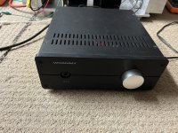
It works! Nothing blew up! 24V@2.5A

 . Plays nice with the WHAMMY. Haven't played with P2 yet, set it at the midpoint, sounds fantastic!
Attachments
The original 12V SMPS brick was isolated from line ground. This looks like the chassis is connected to line (safety) ground, and you have kept V- separate from the chassis. This is important, as V- is actually (2.5A * 0.56Ohm) below the chassis.
Chassis is earthed along with the smps which has an earth, which is also isolated from the -V. No offense taken....I choose wire color based on what day of the week it is, in a previous life working on machines, I found many manufacturers do the same.
- Home
- Amplifiers
- Pass Labs
- Zenductor