
I don't think thermoelectric coolers will really help in this application. Yes, you could run the transistor cooler, but you are going to dump extra heat (because these devices are pretty inefficient) into the heat sink, so now you either run the heat sink a lot hotter, or you need a much larger heat sink, or a fan. Might as well do without the extra heat load from the Peltier cooler, and just use a larger sink or a fan.
Or just put up with 70 to 80 C like I do. No indication that there is a reliability issue, just hot sinks.
Well, 80C is pretty hot... but fundamentally I'm not too worried in the spring/summer/fall. But what what will it do in the summer when we run 90F outside? Do I have to run the AC to keep the room at 78F if I want to run these babies that hot? At 48 cents per KwH we can't afford it cooler.
How hot above ambient can we expect the amp to run when biased at 1.45V?
BTW, I'm waiting for my "extender" heat sinks. I found the digital thermometers (with a probe) that I used when I debugged the Sissy SIT. So, it should be easy to do a before and after. Planning on this weekend to do the baseline -normal heat sinks - measurements. Our daylight ambient is now hovering at 72F.
Oh, this is just part of the fun. Who knows, maybe the amps will get hot enough that I can straighten out the rows of "Drunken Sailor" JFETS.
Last edited:
Can the transformer be connected for 12dB of gain of gain so the amp is non inverting and has a little more gain?
Wouldn't using two (or more) output caps and connecting the positive leads to the the sources of the mosfets give a significantly lower output impedance?
Would picking the lowest Ids jfets for the current source group be worth it to run the follower group below Idss?
Wouldn't using two (or more) output caps and connecting the positive leads to the the sources of the mosfets give a significantly lower output impedance?
Would picking the lowest Ids jfets for the current source group be worth it to run the follower group below Idss?
Last edited:
Yea. Just as when it comes to The Finest Chilli: The Real Hotness is a feature. Not a bug.
🔥🙂👍🔥
But if you really insist on extra cooling for the possibility of the Extra high bias setting? Just do it like i did on my 4 channel ACA mini. Rescue a reasonably big heatsink from an AV- Reciever. And configure the active devices from the back side of the amplifier PCB against the heatsink.
🔥🙂👍🔥
But if you really insist on extra cooling for the possibility of the Extra high bias setting? Just do it like i did on my 4 channel ACA mini. Rescue a reasonably big heatsink from an AV- Reciever. And configure the active devices from the back side of the amplifier PCB against the heatsink.
Attachments
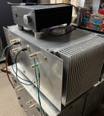
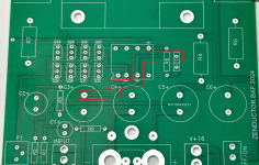
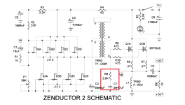
Or....just make it HUUUGE. Take a few months off of DIY audio and it'll take me another few months to catch up. Finished a massive chassis for Zenductor V1, 400VA, 22V, 2.3A bias, used 193V for the inductor. I rolled my own PCBs of course. May have found a discrepancy between schem and board for the new version, as I plan on making it bigger, as usual. Attached are a few pics. It appears the gnd connection of C7 on the schematic does not match the board, on the board it goes to the + of C3...?
Attachments
Last edited:

Very nice, I’m drooling over that industrial, indestructible unit 👍👍
A fancy looking enclosure is nice to have but given a choice I prefer yours since it looks great and will last ( until your next build 😂).
A fancy looking enclosure is nice to have but given a choice I prefer yours since it looks great and will last ( until your next build 😂).
I think you are right. Electrically it probably doesn't make a difference, 0.047 microFarad in series with 6.8mF is still 0.047microFarad. It's odd that the trace (or transformer pin) is labelled 'GND' on the board, but it is not ground.[...] It appears the gnd connection of C7 on the schematic does not match the board, on the board it goes to the + of C3...?
does not match
Welcome to Papaworld.....
that's to keep us on toe-tips, all the time ....

A few days ago I was looking for some bike parts, and...I saw that 48 V power supply/charger for el.bikes. Guess what I was thinking? 😀
Turbo Zenductor
Turbo Zenductor
Decide how much DC bias current you are going to draw from the 48V DC power supply. Choose inductor(s) which can accept this much current. Calculate the maximum possible output power in watts, delivered to an 8 ohm load, when this much bias current is flowing. Calculate the power dissipated in the transistor(s) which drive the inductor(s), at this bias current and with a 48V DC power supply. How many transistors will you need, to stay safely within the safe operating area zones of those transistors? How much heatsinking will you need per transistor?
It might turn out to be quick and simple.
It might turn out to be quick and simple.

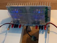
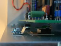
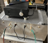
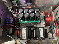
Alright, I've done mine up so it's less likely to


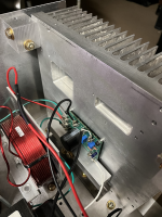
Screwed to a board w/ some sticky button feet, via existing standoffs. I've tapped power just after the switch to feed to a buck converter (fits under the board) to output 6v for the 120 mm fan (nominally a 12v fan). I can't hear the fan unless my ear is < 1 ft from it. I can't hear any fan e-noise coming thru the speakers. Heatsinks are about 125 F (51 c) up near the top, I can find about 140 F (60 c) if I search around to get a reading off the devices or near to them. 1.38 V across the inductor (re-biased). 3D printed a bracket to mount the fan, which was fun, but prob you could manage without (LMK if you want the file).
buck converters - 6 for $9
https://www.amazon.com/dp/B08G4GYNL6?ref=ppx_yo2ov_dt_b_fed_asin_title
cheap fans - 3 for $9
https://www.amazon.com/dp/B0CD7P3S8Q?ref=ppx_yo2ov_dt_b_fed_asin_title
Still sounds great! Now with moderately stabilized mechanical properties.
- tip over / slide around
- scratch furniture
- scald the unwary / burst into flames
Screwed to a board w/ some sticky button feet, via existing standoffs. I've tapped power just after the switch to feed to a buck converter (fits under the board) to output 6v for the 120 mm fan (nominally a 12v fan). I can't hear the fan unless my ear is < 1 ft from it. I can't hear any fan e-noise coming thru the speakers. Heatsinks are about 125 F (51 c) up near the top, I can find about 140 F (60 c) if I search around to get a reading off the devices or near to them. 1.38 V across the inductor (re-biased). 3D printed a bracket to mount the fan, which was fun, but prob you could manage without (LMK if you want the file).
buck converters - 6 for $9
https://www.amazon.com/dp/B08G4GYNL6?ref=ppx_yo2ov_dt_b_fed_asin_title
cheap fans - 3 for $9
https://www.amazon.com/dp/B0CD7P3S8Q?ref=ppx_yo2ov_dt_b_fed_asin_title
Still sounds great! Now with moderately stabilized mechanical properties.
Alright, I've done mine up so it's less likely to
- tip over / slide around
- scratch furniture
- scald the unwary / burst into flames
View attachment 1375741 View attachment 1375742
Screwed to a board w/ some sticky button feet, via existing standoffs. I've tapped power just after the switch to feed to a buck converter (fits under the board) to output 6v for the 120 mm fan (nominally a 12v fan). I can't hear the fan unless my ear is < 1 ft from it. I can't hear any fan e-noise coming thru the speakers. Heatsinks are about 125 F (51 c) up near the top, I can find about 140 F (60 c) if I search around to get a reading off the devices or near to them. 1.38 V across the inductor (re-biased). 3D printed a bracket to mount the fan, which was fun, but prob you could manage without (LMK if you want the file).
buck converters - 6 for $9
https://www.amazon.com/dp/B08G4GYNL6?ref=ppx_yo2ov_dt_b_fed_asin_title
cheap fans - 3 for $9
https://www.amazon.com/dp/B0CD7P3S8Q?ref=ppx_yo2ov_dt_b_fed_asin_title
Still sounds great! Now with moderately stabilized mechanical properties.
Mid 50C's on the heat sinks is standard on Pass amps, huh?
My F5M (no fan) runs about the same 125 F (51 c), but that's hottest point on the sinks for the F5M and coolest point for the ZD2.Mid 50C's on the heat sinks is standard on Pass amps, huh?
F5M might be hotter inside the box, while ZD2 has no inside / outside, so maybe not exactly apples-to-apples...
- Home
- Amplifiers
- Pass Labs
- Zenductor 2 Amp Camp '24 version