I put the new 4565 in place of the 4560 and no change. The power supply is still producing +12 and -10 V rails when the 3525 is powered externally.
Before I shorted neg rail (-68 V) to V+ (pin 8) of the 4560 I had ~ + and - 70 V rails.
All the readings from the pins look good on the 3525, except the outputs 11 and 14 read 0.0078 and 0.0085 respectively.
Nothings seems out of the ordinary when checking the components from the 3525 outputs to the gates of the P.S. FETs.
Something had to change at the 3525. Are you 100% sure that the voltages on it are the same as when you had 70v rails?
This was before the mishap. +/- 70 V rails
Pin 1: -0.0001
Pin 2: 0.4740
Pin 3: 0.0153
Pin 4: 0.1836
Pin 5: 2.0580
Pin 6: 3.8450
Pin 7: 2.0550
Pin 8: 4.9390
Pin 9: 0.8980
Pin 10: 0.0126
Pin 11: 0.0965
Pin 12: 0.0004
Pin 13: 12.397
Pin 14: 0.0783
Pin 15: 12.397
Pin 16: 5.1970
This is now: ~ +/- 11 V rails
Pin 1: 0.0004
Pin 2: 0.4720
Pin 3: 0.0145
Pin 4: 0.1836
Pin 5: 2.0500
Pin 6: 3.8000
Pin 7: 2.0480
Pin 8: 4.9240
Pin 9: 0.9090
Pin 10: 0.0128
Pin 11: 0.0078
Pin 12: 0.0004
Pin 13: 12.667
Pin 14: 0.0085
Pin 15: 12.667
Pin 16: 5.1790
I wasn't. I was getting +12 and -10 V
When I use the secondary ground, both rails are the same magnitude +/- 11.023 V
When I use the secondary ground, both rails are the same magnitude +/- 11.023 V
It's not in a socket, but I will install a socket tomorrow.
I found a couple of new 3525s I dug out that I will try.
Thanks for your help, have a good evening.
I found a couple of new 3525s I dug out that I will try.
Thanks for your help, have a good evening.
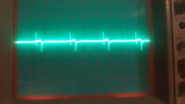
If you have the tutorial, look at the sync pin input (and the other waveforms). Does your sync waveform look about the same?
Yes, the sync pin looks the same as does all the others with the exception of pin 4. The magnitude is the same but, the period of the pulses are 2 div horizontally while in the tutorial they are about 1.5 div per pulse.
Since it's now in a socket, lift the two output terminals to see if it will produce output pulses.
The Clarion has pulldown resistors on the FET drive circuit. Make sure that this amp has them before lifting the output terminals.
The Clarion has pulldown resistors on the FET drive circuit. Make sure that this amp has them before lifting the output terminals.
Does this use a regulation circuit that has the equivalent of U16 that the clarion has?
Are you sure your meter is reading right at 11v?
Are you sure your meter is reading right at 11v?
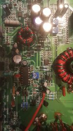
It is close. This has the small transformer that produces the secondary supplies.
I believe: Image = schematic
U8 = U16
R141 and R142 = R112 and R109
This is where I shorted the -rail (R141) to pin 8 of the opamp U9 in the image
For R141 and R142 the side opposite the connection to the optocoupler goes to the small transformer.
Yes, I think the meter is correct. I believe I got the same thing with the scope. When I reconnect both outputs I will check again with both the scope and meter.
With pins 11 and 14 lifted the rails are zero.
Should I reconnect the all the pins of the 3525?
Attachments
Last edited:
Remove the optocoupler equivalent to U16 and see if it builds rail voltage. Just power up for a second or two so you don't get too much rail voltage (with no regulation). The outputs of the 3525 will have to be back in the circuit.
The problem could be that optocoupler, the TL431 or possibly the two other optocouplers in that area (less likely).
- Home
- General Interest
- Car Audio
- Zapco C2K 9.0XD