Perry,
Well, I am back to where I started.
I changed the TL431 and have +/- 70 V rails.
Yesterday, I had DC Offset between the two speaker output terminals.
Left Ch: 2.5 V
Right Ch: 900 mV
So I went through the tutorial and Clarion Schematic to determine where the DC protect circuit is. I am still not sure which it is.
Unfortunately, upon powering up today to do more poking around the DC is around 120 mV on both channels.
Not sure where to start, but thinking maybe I should start trying to locate and disable the particular protection circuits to determine what area is causing the amplifier to go into protect.
What do you think?
So, no audio from the amp?
When you had 120mv on the speaker terminals, was the power supply oscillating (producing rail voltage)?
When you had 120mv on the speaker terminals, was the power supply oscillating (producing rail voltage)?
No audio.
Yes, +/- 70 V.
I was able to reproduce the DC offset by placing the Tri-Path chip in.
It is 2.45 V on ChR and 928 mV on ChL
Yes, +/- 70 V.
I was able to reproduce the DC offset by placing the Tri-Path chip in.
It is 2.45 V on ChR and 928 mV on ChL
L In, pin 5. Clean audio riding on +2 Vdc. ( It is stable ~90% of the time. The other part of the time the amplitude of the audio signal is fluctuating)
R In, Pin 6 No audio just 2.5 Vdc.
R In, Pin 6 No audio just 2.5 Vdc.
Looking at the clarion, it appears that the input to its IC needs 2.5v of bias but the audio should be clean and with no DC before the coupling cap that separates the preamp from the module.
If you pull the module, do you have clean audio on the preamp side of the coupling caps and 2.5v (adjustable with pots) on the module input pins (no module)?
If you pull the module, do you have clean audio on the preamp side of the coupling caps and 2.5v (adjustable with pots) on the module input pins (no module)?
So I checked at the coupling caps and still had no audio on C59 so I followed the op-amps from the preamp input to C59 and by time I got back to C59 there was audio on it. Up until this point I have had no audio there. So while probing the outputs of the op-amps I must have changed something.
Just to be clear, when referring to component designations, I am using the Clarion schematic, not the actual ones on my board.
So now I have clean audio, no DC, on the preamp side of both channels coupling caps.
If I set P1 and P2 to have 2.5 Vdc on the pins 5 and 6, I have audio riding on 2.5 Vdc.
If the tripath module is in I have no audio on the speaker terminals but I do have 2.5 Vdc across them for both channels.
If I set P1 and P2 Full CW, so that I have no DC on 5 and 6, of course I have audio with no dc component at 5 and 6.
If the Tripath module is in I still have no audio on the speaker terminals and I still have 2.5 Vdc across the terminals for both channels.
Upon immediate start up it goes to 5.24 Vdc. With each flash of the protect led it goes from 5.24 V to -0.16V to 5.24 V then stays at 5.24 V when the protect led stays illuminated.
Edit: Voltage was taken at pin 4 (Mute). Looking back at the schematic I see there is also a HMute at pin 35. I just wanted to be clear.
Edit: Voltage was taken at pin 4 (Mute). Looking back at the schematic I see there is also a HMute at pin 35. I just wanted to be clear.
Last edited:
Bridging U6, pin 3-4 (clarion diagram), will prevent the mute from going high (mute) but it could be risky.
Does the PS shut off when the amp goes into mute?
The HMUTE is an output from the IC.
Does the PS shut off when the amp goes into mute?
The HMUTE is an output from the IC.
I will give it a try in the morning. Should I leave the Tripath module out?
Up to this point I have been having to power the power supply externally through pin 13 and 15 of the 3525.
Up to this point I have been having to power the power supply externally through pin 13 and 15 of the 3525.
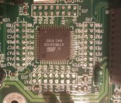
Doing some tracing and best I can tell HMUTE (pin 35) goes to a 1K resistor then to PA1 (pin 50) of the ATmega103 microcontroller. I can not find any optocoupler that it is tied to, at least on the module side of the microcontroller, like in the Clarion schematic.
Same with MUTE (pin 4), it goes to a 1K resistor then to PC4 (pin 39) of the micro controller.
Same with MUTE (pin 4), it goes to a 1K resistor then to PC4 (pin 39) of the micro controller.
Not yet. I emailed them and used there contact link on the website and nothing.
I will make a phone call Monday and see if I can talk to an actual person.
I will make a phone call Monday and see if I can talk to an actual person.
- Home
- General Interest
- Car Audio
- Zapco C2K 9.0XD