I don't know how to quote other posts from here, but like I mentioned in post #7 , nothing really. Checked, it was shorted, started looking for something obvious, checked continuity again and read 70 ohms and counted up. Removed the pcb from case to check under it for any possibly way for B+ to short to Neg, didn't see anything.
Board is still out of case and still same behavior with respect to continuity between B+ and ground. (70 ohms and counting). Still have no idea why or how B+ was shorted to ground (0.5 ohms) when it put the power supply into protect.
Board is still out of case and still same behavior with respect to continuity between B+ and ground. (70 ohms and counting). Still have no idea why or how B+ was shorted to ground (0.5 ohms) when it put the power supply into protect.
Ok, to clarify... the amp is now powering up (but going into protect) with a 10 amp fuse. Is that true?
Yes sir,
With head lamp in line, I put power to it, green led comes on for 1 second, headlamp flashes, amp goes into protect. (all within about three seconds)
It will do the same and stay in protect with a 10 amp fuse in line as with the head lamp in line.
While in protect the fans are running, the, what I think is the, secondary supply is trying to do something as mentioned before.
Some times it goes through this process two times automatically then stays locked into protect on third attempt, (takes about ten seconds total).
Some times it locks into protect the first time (3 seconds).
The only time it wouldn't do this, (would not start at all), is when B+ was shorted to ground.
Which terminal of the PS driver IC is shutting it down. If you don't know, post the DC voltage on all terminals when it's in protect.
Pin 1:
Pin 2:
Pin 3:
Pin 4:
Pin 5:
Pin 6:
Pin 7:
Pin 8:
Pin 9:
Pin 10:
Pin 11:
Pin 12:
Pin 13:
Pin 14:
Pin 15:
Pin 16:
Pin 1:
Pin 2:
Pin 3:
Pin 4:
Pin 5:
Pin 6:
Pin 7:
Pin 8:
Pin 9:
Pin 10:
Pin 11:
Pin 12:
Pin 13:
Pin 14:
Pin 15:
Pin 16:
Pin 1: 0.0003
Pin 2: 0.0003
Pin 3: 0.0003
Pin 4: 0.0003
Pin 5: -0.0002
Pin 6: 0.0003
Pin 7: -0.0001
Pin 8: 0.0003
Pin 9: 0.0003
Pin 10: 0.0003
Pin 11: 0.0001
Pin 12: 0.0003
Pin 13: 0.3300
Pin 14: 0.0002
Pin 15: 0.2796
Pin 16: 0.0003
Pin 2: 0.0003
Pin 3: 0.0003
Pin 4: 0.0003
Pin 5: -0.0002
Pin 6: 0.0003
Pin 7: -0.0001
Pin 8: 0.0003
Pin 9: 0.0003
Pin 10: 0.0003
Pin 11: 0.0001
Pin 12: 0.0003
Pin 13: 0.3300
Pin 14: 0.0002
Pin 15: 0.2796
Pin 16: 0.0003
Is the microcontroller the same number as the one in the clarion manual?
If so, do you have 5v on the VDD pin?
If so, do you have 5v on the VDD pin?
That is within what the microcontroller can withstand. You can look at the regulator components to see if they're within tolerance but I don't think that should be a problem.
I'd disconnect the transistor that's feeding pins 13 and 15 of the 3525 (Q3 on the diagram) and drive those pins with 12v (remote).
Leave the module out of the amp.
Be careful when applying voltage. Be ready to remove B+ if there is a problem. Does the amp draw excessive current?
I'd disconnect the transistor that's feeding pins 13 and 15 of the 3525 (Q3 on the diagram) and drive those pins with 12v (remote).
Leave the module out of the amp.
Be careful when applying voltage. Be ready to remove B+ if there is a problem. Does the amp draw excessive current?
I am having trouble figuring out which transistor is connected to 13 and 15. None of them are connected directly and there are very few visible traces on this board.
It does seem that 13 and 15 are connected to an optocoupler. I will look more tomorrow.
Thanks
It does seem that 13 and 15 are connected to an optocoupler. I will look more tomorrow.
Thanks
Install the IC in a socket and pull pins 13 and 15 out of the socket and connect the 12v to the lifted terminals.
I found the transistor feeding pins 13 and 15 of the 3525. It happens to be Q4 a 6717A in this amp. I will pull it and supply 12 V remotely tomorrow.
I checked the voltage on the emitter of Q4 as the amp powered up and got 15.6 V for a fraction of a second before the amp went into protect.
Another note, the circuits tied to pins 11 and 14, outputs A and B respectively of the SG3525, match the Clarion diagram, with the exception of the transistors and FETs part numbers, but the layout is the same.
Pulled Q4 applied 12.4 V to emitter pad Q4.
Pin 1: -0.0001
Pin 2: 0.4740
Pin 3: 0.0153
Pin 4: 0.1836
Pin 5: 2.0580
Pin 6: 3.8450
Pin 7: 2.0550
Pin 8: 4.9390
Pin 9: 0.8980
Pin 10: 0.0126
Pin 11: 0.0965
Pin 12: 0.0004
Pin 13: 12.397
Pin 14: 0.0783
Pin 15: 12.397
Pin 16: 5.1970
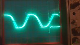
Attached is the image of the signal at the gate of the P.S. FET. 0.5 V/div and 5 uS/div
It is producing rail voltage of "V+amp" at 69.6 V and "V-amp" at -67.7 V
Pin 1: -0.0001
Pin 2: 0.4740
Pin 3: 0.0153
Pin 4: 0.1836
Pin 5: 2.0580
Pin 6: 3.8450
Pin 7: 2.0550
Pin 8: 4.9390
Pin 9: 0.8980
Pin 10: 0.0126
Pin 11: 0.0965
Pin 12: 0.0004
Pin 13: 12.397
Pin 14: 0.0783
Pin 15: 12.397
Pin 16: 5.1970
Attached is the image of the signal at the gate of the P.S. FET. 0.5 V/div and 5 uS/div
It is producing rail voltage of "V+amp" at 69.6 V and "V-amp" at -67.7 V
Attachments
Can you see any reason that it was shutting down? Missing voltage somewhere, DC on the output...
Did you check the regulator components for the microcontroller to see what the regulated voltage should be?
Did you check the regulator components for the microcontroller to see what the regulated voltage should be?
I haven't found any reason why it is shutting down.
Speaker terminals have 150 mV and 125 mV. This amp has pots to adjust dc offset, but moving them through there full range doesn't change anything.
Reading the datasheet on the microcontroller it gives its operating voltage as 4.0 to 5.5 V. I've got 6.2 V on Vcc. Maybe that has something to do with it?
This amp does not use the 7805 as the regulator as in the clarion schematic. I am not sure what it is using. The ~ 6.2 voltage is present on one leg of the small transformer but I have not been able to trace its path to the microcontroller yet.
I could be wrong, but I think this amp is using LM431s for the under/over voltage protection. The LM431 on the higher voltage side is connected to a pot that changes the voltage on that LM431. It is currently turned all the way up and I don't know what it is supposed to read on the pins of the LM431.
I tried different pot positions and while it changed the readings on the anode, cathode and reference, it had no effect on the amplifier going into protect or not.
I did find a pad on the pcb labeled "12V Reference" that has 55 V on it so not sure about that.
So from the post #32 we can conclude that power supply is fine?
The absolute maximum voltage for the IC is 6.6v.
What about the ± regulated voltages?
The TL431 in the Clarion is for the rail voltage.
Is the 12v reference 12v above the negative rail like VN12 on the Clarion diagram?
What about the ± regulated voltages?
The TL431 in the Clarion is for the rail voltage.
Is the 12v reference 12v above the negative rail like VN12 on the Clarion diagram?
To answer the questions in #35
Regulated Voltages :
15.67 V and -14.20 V going to all the op-amps
6.193 V
13.50 V
16.34 V referenced to negative rail
The 12V reference is 12V above the negative rail.
While poking around to try and answer these questions I fried a NJM4560 in the power supply I shorted negative rail voltage to pin 4 V-.
I can't find info on the package type. The body measures 5.0 x 5.0 mm. Any ideas on pkg. type?
If I have to order the 4560 I cant find anything with this pkg size.
Will a TL072 work in its place, assuming the pins will line up on the pads?
Most characteristics look ~ the same. The Gain Bandwidth is lower in the TL072 4 MHz vs 10 MHz for the 4560.
I don't know how the bad op-amp is being used. The NJM45xx op-amps are typically used when a circuit requires a stronger drive.
The package appears to be a DMP8.
The package appears to be a DMP8.
- Home
- General Interest
- Car Audio
- Zapco C2K 9.0XD