I made short versions of the three membranes above.
1+2 with fill was 0.77grams,
1+2 without fill was 0.53grams and
1+0 without fill was 0.43grams.
I corrugated them with 0.5mm 80 cogs rollers.
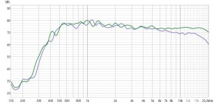
Here's some measurements with a 1+2 with fill corrugated with 1.0 mm 40 cogs rollers as reference (green trace).
SPL at 0.3m:

As I see it, the 1+2 with filler and 0.5mm cogs (blue trace) is the winner. One thing that is different from the 1.0mm version is that I removed any glue residue on the 0.5mm versions.
I don't think it was the reduced weight as such that made the difference; the lighter 1+2 and 1+0 without fillers were worse above 16kHz.
Distortion at 0.3m:

Here the SPL winner above (blue trace) has higher THD as the 2+1 with filler and 1.0mm corrugation (green trace).
This can of course be unrelated to the cog sizes; a lot of membranes has to be tested to get secure results but time and effort are not endless.
I will however test 1+2 membranes corrugated with 0.67mm cogs and 0.75mm cogs.
So what about foam vs EPDM?

The two purple one are foam at 0.3m (3) and 1.0m (4). Compared to the two other EPDM (1) and (3) at 0.3 and 1.0m respectively.
I reckon that the foam surround even if softer, has longer contact with the membrane than the EPDM surround, the EPDM having a more pointy contact surfaces.
The take away from this rabbit hole is the keep the EPDM and the 1+2 with filler corrugation but with glue residual removal.
I'll need however, to test corrugations between 0.5 and 1.0mm. That is 0.67 and 0.8mm cogs.
1+2 with fill was 0.77grams,
1+2 without fill was 0.53grams and
1+0 without fill was 0.43grams.
I corrugated them with 0.5mm 80 cogs rollers.
Here's some measurements with a 1+2 with fill corrugated with 1.0 mm 40 cogs rollers as reference (green trace).
SPL at 0.3m:
As I see it, the 1+2 with filler and 0.5mm cogs (blue trace) is the winner. One thing that is different from the 1.0mm version is that I removed any glue residue on the 0.5mm versions.
I don't think it was the reduced weight as such that made the difference; the lighter 1+2 and 1+0 without fillers were worse above 16kHz.
Distortion at 0.3m:
Here the SPL winner above (blue trace) has higher THD as the 2+1 with filler and 1.0mm corrugation (green trace).
This can of course be unrelated to the cog sizes; a lot of membranes has to be tested to get secure results but time and effort are not endless.
I will however test 1+2 membranes corrugated with 0.67mm cogs and 0.75mm cogs.
So what about foam vs EPDM?
The two purple one are foam at 0.3m (3) and 1.0m (4). Compared to the two other EPDM (1) and (3) at 0.3 and 1.0m respectively.
I reckon that the foam surround even if softer, has longer contact with the membrane than the EPDM surround, the EPDM having a more pointy contact surfaces.
The take away from this rabbit hole is the keep the EPDM and the 1+2 with filler corrugation but with glue residual removal.
I'll need however, to test corrugations between 0.5 and 1.0mm. That is 0.67 and 0.8mm cogs.
I've been battling with ChatGPT about the tweeter membrane.
These are the conclusions:
Helmholtz's resonator frequency:
Speaker cloth on the inside of the front plate can lower Q for the Helmholtz's resonator frequency.
Mostly by soften the phase shift in the cavity/opening.
It will also make the front cavity marginally smaller and thus push the Helmholtz's resonator frequency a couple of hundred Hertz.
Recommended placement:
Inside the front plate (between the front plate and the diaphragm/cavity).
Reasons:
Corrugation:
Desired corrugation for the tweeter membrane is a depth of 0.2 – 0.7 mm and a pitch of 1.5 – 3.0 mm.
To be able to corrugate such a membrane and then bake it, I must use thinner aluminium foil in the "sandwich"; only 20µm.
The sandwich will otherwise not be corrugated deep enough.
Goal: High rigidity, low mass, good transient response.
Recommended values:
Vertical tension of the membrane:
The vertical tension of the membrane needs to be between 1 and 5N. To accomplish that I need to make a tensioning mechanism at the top of the speaker.
This tension structure has to be peripendular to the speaker and accomodate a dynamometer to measure the tension before fastening the membrane.
Distance between the aluminium strips:
The distance between the aluminium strips needs to be much less than the current 0.5mm. In the table above is also listed the effect the distance can have on distortion.
I will aim for 0.25mm as it will be easier to do it in Silhouette Design as it is half of the current distance.
In order succeed with the cuts, I will have to go very slow.
These are the conclusions:
Helmholtz's resonator frequency:
Speaker cloth on the inside of the front plate can lower Q for the Helmholtz's resonator frequency.
Mostly by soften the phase shift in the cavity/opening.
It will also make the front cavity marginally smaller and thus push the Helmholtz's resonator frequency a couple of hundred Hertz.
Recommended placement:
Inside the front plate (between the front plate and the diaphragm/cavity).
Reasons:
- Smoother airflow:
Placing the fabric inside the front plate reduces abrupt air turbulence at the openings. This results in lower distortion and a smoother transition between the resonance frequency and surrounding frequencies. - Controlled acoustic impedance:
Fabric inside the plate provides a more controlled acoustic impedance, effectively damping resonance without causing audible reflections from the surface. - Diaphragm protection:
Placement inside the front plate also protects the corrugated diaphragm from potential particles or direct physical impact.
- Very thin and porous:
To avoid increased distortion, the fabric must be extremely thin and acoustically transparent (for example, acoustic filtering material made from polyester, very thin nylon weave, or acoustic mesh designed for microphones or speakers). - Stretched and securely mounted:
The fabric should be mounted slightly stretched and secured to prevent vibrations, thus minimizing potential self-resonance or mechanical interference with the diaphragm.
Corrugation:
Desired corrugation for the tweeter membrane is a depth of 0.2 – 0.7 mm and a pitch of 1.5 – 3.0 mm.
To be able to corrugate such a membrane and then bake it, I must use thinner aluminium foil in the "sandwich"; only 20µm.
The sandwich will otherwise not be corrugated deep enough.
Goal: High rigidity, low mass, good transient response.
Recommended values:
- Corrugation depth: 0.2 – 0.7 mm
- Shallower corrugations (around 0.3 mm) yield higher frequency response and reduce micromodulation.
- Too deep corrugations (>0.7 mm) may reduce frequency response in the 10–20 kHz range.
- Pitch (corrugation spacing): 1.5 – 3 mm
- Denser corrugations (1.5–2 mm) provide better control and reduce breakup effects.
- Wider spacing (>3 mm) may increase breakup, but could enhance sensitivity in certain frequency bands.
Vertical tension of the membrane:
The vertical tension of the membrane needs to be between 1 and 5N. To accomplish that I need to make a tensioning mechanism at the top of the speaker.
This tension structure has to be peripendular to the speaker and accomodate a dynamometer to measure the tension before fastening the membrane.
Since 2nd Harmonic Distortion (2HD) is the dominant component, we distribute THD as follows:
- 2HD ≈ 60% of THD
- 3HD ≈ 30% of THD
- Higher-order distortion (4HD, 5HD, ...) ≈ 10% of THD
| Membrane Tension (N/m) | 2HD at 0.3 mm PET (dB) | 2HD at 0.4 mm PET (dB) | 2HD at 0.5 mm PET (Reference) (dB) | 3HD at 0.3 mm PET (dB) | 3HD at 0.4 mm PET (dB) | 3HD at 0.5 mm PET (dB) | Higher HD at 0.3 mm PET (dB) | Higher HD at 0.4 mm PET (dB) | Higher HD at 0.5 mm PET (dB) |
|---|---|---|---|---|---|---|---|---|---|
| 0.5 N/m | -62 dB | -59 dB | -55 dB | -65 dB | -63 dB | -60 dB | -69 dB | -67 dB | -65 dB |
| 1.0 N/m | -65 dB | -61 dB | -57 dB | -67 dB | -65 dB | -62 dB | -71 dB | -69 dB | -67 dB |
| 1.5 N/m | -67 dB | -63 dB | -59 dB | -69 dB | -67 dB | -64 dB | -73 dB | -71 dB | -69 dB |
| 2.0 N/m | -69 dB | -65 dB | -61 dB | -70 dB | -68 dB | -65 dB | -74 dB | -72 dB | -70 dB |
| 2.4 N/m (max) | -70 dB | -66 dB | -62 dB | -71 dB | -69 dB | -66 dB | -75 dB | -73 dB | -71 dB |
Distance between the aluminium strips:
The distance between the aluminium strips needs to be much less than the current 0.5mm. In the table above is also listed the effect the distance can have on distortion.
I will aim for 0.25mm as it will be easier to do it in Silhouette Design as it is half of the current distance.
In order succeed with the cuts, I will have to go very slow.
Perhaps. I don't how well the tension values correlate in reality.
2.4N/m is a lot, it would be the equivalent of hanging a 528gram weight at the bottom of the membrane😵.
I reckon that I will start on the lower end...
2.4N/m is a lot, it would be the equivalent of hanging a 528gram weight at the bottom of the membrane😵.
I reckon that I will start on the lower end...
I changed the spacing between the aluminium strips from 0.5 to 0.25mm.
I have also made corrugation rollers with other pitch and depth:
Corrugation rollers:
The first row is the original. The module refers to how the cog wheel is parametrized in Fusion.
The actual depth of the membrane when it is mounted in the speaker is less than above due to that the membrane is stretched.
All rollers have the same diameter.
I have also made corrugation rollers with other pitch and depth:
Corrugation rollers:
| # cogs | Module | Pitch (mm) | Depth (mm) |
| 40 | 1 | 3.3 | 2.25 |
| 50 | 0.8 | 2.6 | 1.75 |
| 60 | 0.67 | 2.2 | 1.50 |
| 80 | 0.5 | 1.6 | 1.15 |
The actual depth of the membrane when it is mounted in the speaker is less than above due to that the membrane is stretched.
All rollers have the same diameter.
Last edited:
Some measurements:
SPL

The 60 (orange) and 80 (light green) cog membranes has to uneven SPL response for my liking.
Distortion (THD):

The 80 (red and light green) cogs membranes has too high distortion. I suspect that the reason for it is that the membrane is too thin so that the suspension just doesn't "grab" the membrane.
The conclusion of the above is that 0.5mm spacing and 40 cogs together with 0.25mm spacing and 50 cogs is almost tthe same.

0.25mm spacing and 50 cogs has a slightly more even response.
THD

Hard to chose a winner based on THD.
Distortion 3HD:

So the winner is 0.25mm spacing and 50 cogs (blue) corrugation.
SPL
The 60 (orange) and 80 (light green) cog membranes has to uneven SPL response for my liking.
Distortion (THD):
The 80 (red and light green) cogs membranes has too high distortion. I suspect that the reason for it is that the membrane is too thin so that the suspension just doesn't "grab" the membrane.
The conclusion of the above is that 0.5mm spacing and 40 cogs together with 0.25mm spacing and 50 cogs is almost tthe same.
0.25mm spacing and 50 cogs has a slightly more even response.
THD
Hard to chose a winner based on THD.
Distortion 3HD:
So the winner is 0.25mm spacing and 50 cogs (blue) corrugation.
Attachments

A note on the suspension material.
Here's what ChatGPT had to say about:

Here's what ChatGPT had to say about:
If you press two pieces of foam used for dust sealing together, why doesn't they compress equal?
I then asked for a table comparing the properties compared to EPDM and open cell foam:When two pieces of sealing foam are pressed together, they typically don't compress equally due to variations in material properties, structural differences, surface conditions, and external factors during compression. Specifically, the unequal compression can be explained scientifically by the following factors:
1.
Foams, even if visually identical, often vary slightly in density and microstructure. Slight differences in pore size, distribution, and cell-wall thickness lead to differences in stiffness and compressibility. A denser or more structurally robust foam will compress less than a softer or less dense foam under identical force.
2.
Foam materials exhibit highly nonlinear elastic and viscoelastic behavior. Even minor variations in load distribution can cause disproportionate deformation due to the nonlinear stress-strain curve. Initially, foam deformation is rapid, and then resistance increases significantly as cell walls collapse or compact.
3.
Minor surface irregularities or variations in surface flatness cause uneven pressure distribution. The foam with a smoother or more uniform surface might experience more uniform and thus different compression compared to the foam with irregularities.
4.
Many foams are viscoelastic, meaning their deformation depends on both the magnitude and duration of applied force. Variations in viscoelastic properties such as relaxation times and creep behavior can lead to different compression responses under sustained loading.
5.
Temperature, humidity, and aging can alter foam properties significantly. One foam piece might have experienced slightly different environmental exposure, affecting stiffness, elasticity, and consequently compression behavior.
6.
Differences in frictional interaction at interfaces can cause asymmetrical deformation. If one side adheres slightly more or has a different friction coefficient, compression distribution will not be symmetrical.

Since it came in another thread, I have some update on my corrugation method above:
As the membrane and 40µm aluminium foil has slighty different coefficients of expansion and to keep it from sliding from side to side during corrgation, it's wise to only tape the membrane to the start of the membrane and then have paper/tape support along the edges.
The paper should be over the membrane so the membrane will come lose really easy.

As I'm baking the membrane, I use heat resistant tape.
The 40µm aluminium foil I use is really for hookahs!A couple of rabbit holes later...
I've managed to bake membranes with the 3M 74 PET film.
I use 40µm aluminium foils with the membrane in the middle like a sandwich.
View attachment 1428034
As the membrane and 40µm aluminium foil has slighty different coefficients of expansion and to keep it from sliding from side to side during corrgation, it's wise to only tape the membrane to the start of the membrane and then have paper/tape support along the edges.
The paper should be over the membrane so the membrane will come lose really easy.
As I'm baking the membrane, I use heat resistant tape.
I have also tested the proposed Helmholtz's resonator mitigation; I put strips of this between the magnets on the front plate.

It didn't do any good:

Distortion was more or less the same.
The 0.25mm spacing and 50 cogs membrane (teal) could actually be used, after some EQ that is.
I also tested different tensions as suggested.


Teal, same as above, is without barely any tension, blue is with 0.5N and brown is with 1.5N. So much for the tension!
I will use 0.25mm spacing and 50 cogs for the mid membrane as well.
With all these investigations done, it's finally time to make some long membranes.
So no more rabbit holes...
It didn't do any good:
Distortion was more or less the same.
The 0.25mm spacing and 50 cogs membrane (teal) could actually be used, after some EQ that is.
I also tested different tensions as suggested.
Teal, same as above, is without barely any tension, blue is with 0.5N and brown is with 1.5N. So much for the tension!
I will use 0.25mm spacing and 50 cogs for the mid membrane as well.
With all these investigations done, it's finally time to make some long membranes.
So no more rabbit holes...
Good data! And good to know that the corrugations should not be too small.
And in this post you mention that you had some 25 um aluminized mylar (15 um alu + 10 um mylar). Do you know if there was an adhesive layer or if the alu was attached with say vacuum depositioning? And if it is without a heavy adhesive layer, where did you buy it?
I'm thinking about reducing weight for my planar membrane, and if I do decide to use a solid alu backing then the backing will act as a heatsink so kapton vs mylar shouldn't make much of a difference. And a major part of the weight is the adhesive, so if I could get my grubby hands on some aluminized mylar / PET that does not have any significant adhesive weight then that would be very interesting to try.
Last edited:
It's aluminized, not glued.
I also have 5, 10 and 12.5µm. I don't know the PET/aluminium ratio of those though. Perhaps Mike knows at Free Flight Supplies.
I also have 5, 10 and 12.5µm. I don't know the PET/aluminium ratio of those though. Perhaps Mike knows at Free Flight Supplies.
I also have 5, 10 and 12.5µm. I don't know the PET/aluminium ratio of those though. Perhaps Mike knows at Free Flight Supplies.
In the link under MYLAR COVERING MATERIAL/FOIL, I assume that the 5, 10 and 12.5 µm aluminized mylar has a very thin aluminum layer since the gram per square metre is the same for clear vs aluminized mylar. In my measurements, aluminum weighs roughly twice as much as mylar at the same volume, so if the aluminization was thicker then it should weigh more.
Since misprints area always a possibility, I sent an email to Mike to se if he knows what the aluminum thickness is.It's aluminized, not glued.
I also have 5, 10 and 12.5µm. I don't know the PET/aluminium ratio of those though. Perhaps Mike knows at Free Flight Supplies.
Mike was quick in answering:Since misprints area always a possibility, I sent an email to Mike to se if he knows what the aluminum thickness is.
The film thickness is microscopic! It adds no weight to the film. Hold it up to the light and you can see through it.
Hopefully the 25 µm aluminized PET (15 µm alu + 10 µm PET) will be better then.
Some update on the corrugation. I've decided to only have one layer of the 40µm baking helper aluminium.
When rolled up, the next turn will enclose the membrane to baked anyway.
By doing so I have better control of the centering of the membrane on the helper aluminium when cranking the rollers.
I've also design a separate feeder for the membrane, the lid, 25mm (red) or 55mm (yellow), is depending if it's the tweeter or mid membrane that are to be corrugated:


I got some 3M 56 tape. It's a little bit thicker than the 74 tape so I thought it would suit for the mid membrane.
But, if ChatGPT is to be trusted, it's the other way around:
So I just got me another rabbit hole...
Some update on the corrugation. I've decided to only have one layer of the 40µm baking helper aluminium.
When rolled up, the next turn will enclose the membrane to baked anyway.
By doing so I have better control of the centering of the membrane on the helper aluminium when cranking the rollers.
I've also design a separate feeder for the membrane, the lid, 25mm (red) or 55mm (yellow), is depending if it's the tweeter or mid membrane that are to be corrugated:
I got some 3M 56 tape. It's a little bit thicker than the 74 tape so I thought it would suit for the mid membrane.
But, if ChatGPT is to be trusted, it's the other way around:
Impact on Frequency Response:
- 3M 56, with significantly thicker PET film (0.025 mm compared to 0.013 mm for 3M 74), will be stiffer with higher mechanical strength.
- Typically results in a higher resonance frequency of the diaphragm.
- Improved diaphragm stability at higher frequencies, potentially resulting in enhanced high-frequency performance.
- However, thicker and stiffer film might introduce more pronounced resonances at certain frequencies, depending on the overall design and tension.
- 3M 74, with thinner film and lower breaking strength, is likely to exhibit lower resonance frequency.
- May produce a somewhat smoother and softer frequency response in the mid-to-high-frequency range.
- Thinner film may deform more readily at high amplitudes, potentially limiting maximum performance in the treble range.
Impact on Distortion:
- 3M 56 (higher mechanical stiffness):
- Likely to have lower distortion at moderate amplitudes due to reduced diaphragm deformation under load.
- Reduces nonlinear deformation, generally resulting in cleaner sound and lower Total Harmonic Distortion (THD), especially at higher frequencies.
- 3M 74 (thinner, more flexible film):
- More susceptible to deformation, thus potentially higher distortion at elevated amplitudes.
- Possibly higher THD under strong load conditions.
Conclusion and Recommendation:
- Choose 3M 56 if maximum mechanical rigidity, lower distortion, and potentially improved high-frequency performance are priorities. Ideal for applications demanding high linearity and stable performance in the treble range.
- Choose 3M 74 if extremely low weight and flexibility are prioritized, though with a potential trade-off of slightly higher distortion at higher amplitudes and a smoother frequency response.
Overall, 3M 56 is better suited for applications requiring higher mechanical stability and linear performance in the treble frequencies.
So I just got me another rabbit hole...
Attachments
On the topic of corrugation, if you have a problem that the tweeter membrane does not keep centered then you might try to add a funnel in the front with the tweeter membrane width + 1 mm or so:

Works great for me, the stiffer 30 um alu holds it in place such that the corrugations are nice and parallel.
But also another thing I have wondered, when you don't use the metallized PET film and instead use thin film + thin aluminum, what adhesive do you use? The lightest yet adhesive I have tried has been the 3M 77 spray, but a coat of that still weighs roughly as much as 9 um of mylar, so it would be interesting if there was a lighter adhesive available.
This thread allegedly claims that Magnepan uses / recommends 3M 3NF, which I have not tried. It would be interesting if 3nf is ligther than the 77 spray.
Hmm if ur looking for mylar+alu laminated foils, i got quite a few. but i dislike etching... i got 9-12 9 alu 12 mylar, and i believe 12/12 and 25-23 and some others... problem is i cant find the data sheets anymore 🙁 since they dont sell it anymore and my email box is a mess.. but if interested i can look it up i think
The length of the feeder for the corrugation helper aluminium is 75mm and for the membrane helper 35mm. I will soon find out if that's enough.
As I'm using 3M 74 film and 3M 56 film, I don't need no additional adhesive; the intrinsic Thermosetting Rubber does the trick.
As the backing is PET, I can corrugate and bake the membranes and then the Thermosetting Rubber for sure helps as well.
As for the weight of polyester and Thermosetting Rubber:
When it comes to 3M 30NF, Wrinex knows all about it!
I don't think OllBoll intends to etch the mylar+alu laminated foils, they will be used as backing only.
As I'm using 3M 74 film and 3M 56 film, I don't need no additional adhesive; the intrinsic Thermosetting Rubber does the trick.
As the backing is PET, I can corrugate and bake the membranes and then the Thermosetting Rubber for sure helps as well.
As for the weight of polyester and Thermosetting Rubber:
Tape Polyester Film (g/m²) Adhesive (g/m²) Adhesive Weight % 3M 74 17.94 7.0 ~28% 3M 56 34.5 39.0 ~53%
Tests will tell.This difference in adhesive content significantly affects the mechanical and acoustic properties of the tapes.
When it comes to 3M 30NF, Wrinex knows all about it!
I don't think OllBoll intends to etch the mylar+alu laminated foils, they will be used as backing only.
i would highly recommend he will not etch 🙂 (just because its an complete hell , and messy, it will cost you a few sweaters 🙂 ) although i got some foils he might want to use, to be fair i think the whole beefing up with extra weight is not a good idea at all. you already have not enough top end when making them longer, then your most active driver that does top end is at floor level, i made many tweeters with 30 micron alu and it does reach 15-18 khz. somehow it does not sound at all the same as the 15 or 12 (or 7 micron). i am sure there is a thickness that does most , some stiffness some damping while still sounding nice at the top end. i tried a foil with overlapping coils etc and it sucked all the efficiency and life out of it...you can try, but i think you keep in mind that if you make it 4 times longer. you might not actually need all that weight but you need is top end. since thats the piece that wont add onn, and its already low with the heavy foils. in a short foil. drops of at 11Khz
this is a tiny thing i made today, for ther montior 9 cm long version one measurement on axis one when standing up. this will look insane different with 80-140 cm long one. this is not gated so some of the lower end would be lower 🙂
this is a tiny thing i made today, for ther montior 9 cm long version one measurement on axis one when standing up. this will look insane different with 80-140 cm long one. this is not gated so some of the lower end would be lower 🙂
Attachments
Last edited:
- Home
- Loudspeakers
- Planars & Exotics
- Yet another Planar Magnetic Line Source, the SMAPPP