Be aware that the paper backing might slip if the traces heat up.
Amazing how much test and trying you perform.
Amazing how much test and trying you perform.
Yes, I will for sure do measurements with a lot of power as well.
If it measure well enough at 1W that is.
If it measure well enough at 1W that is.
The same test with quilt wadding:I suspected that the foam strips were not even compressed, it would seem like the compressing side is compressed more than the stationary side and by doing so gets the membrane not exactly in the middle.
i had the exact same problem, making the foil to close to the magnets or to far away and creates efficiency problems between panels 🙁I suspected that the foam strips were not even compressed, it would seem like the compressing side is compressed more than the stationary side and by doing so gets the membrane not exactly in the middle.
in a later prototype i just used single ended sticky foam type at the correct height. and then both measured the same.. Quilt wadding hmm i might need to look that up. ! its like wadding for inside a jacked or pillow etc ?
if using foam making it not compress as much worked sort of. less troubles but i dont know if it might be to little compression over time
So far I haven't measured any differences. It's probably just Audiophilia Nervosa.
I think the quilt wadding in those dimensions are for furniture, for example the sides of a sofa.
I think the quilt wadding in those dimensions are for furniture, for example the sides of a sofa.

My goals are at least -60dB THD (that's 0.1%) from 300Hz to 3kHz for mid and from 2kHz to 20kHz for the tweeter, so there are a lot of testing.Amazing how much test and trying you perform.
And when I change any input parameter I have to retest with all types of carriers.
I'm now done with measurements, for a while anyway.
And there's a winner!
With EPDM P-profiles as surround and two sided membranes with 3mm 14µm conductive traces on one side and full 6µm aluminium foil on the other.
The EPDM P-profile was easy to cut to the correct widths and easy to apply:

Below are comparision between the previous best membranes with foam and one sided aluminium membranes with aluminium fillings 0.5mm apart.
(You can find the measurements and others here.)
Mid BOPP membrane (new 3 and old 10):


Tweeter PEN membrane (new 7 and old 11)


So now it's the full length membranes that has to be made, but they will have to wait for another year.
And there's a winner!
With EPDM P-profiles as surround and two sided membranes with 3mm 14µm conductive traces on one side and full 6µm aluminium foil on the other.
The EPDM P-profile was easy to cut to the correct widths and easy to apply:
Below are comparision between the previous best membranes with foam and one sided aluminium membranes with aluminium fillings 0.5mm apart.
(You can find the measurements and others here.)
Mid BOPP membrane (new 3 and old 10):
Tweeter PEN membrane (new 7 and old 11)
So now it's the full length membranes that has to be made, but they will have to wait for another year.
Attachments
I'm now done with measurements, for a while anyway.
And there's a winner!
With EPDM P-profiles as surround and two sided membranes with 3mm 14µm conductive traces on one side and full 6µm aluminium foil on the other.
The EPDM P-profile was easy to cut to the correct widths and easy to apply:
Awesome find!
What specific brand of EPDM profiles did you buy? I might as well buy a roll myself and try it out too.
Next hurdle, making 240 cm long membranes.
But it is nice to have something to do indoors when the outdoor temperature is below -15° in the morning and the summer time pool parties are far far away:

Out of two shelf boards 30cm by 246cm I make a jig.
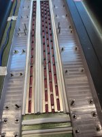
Here's the bottom board with alignment screws:

I use a 15cm wide 100µm aluminium foil as guidance and to keep the surface washable:


I tape down the 15cm wide milk paper, this will be the cutting mat when I later do the cutting with the SC5.


I then spray the 3M 77 glue on the milk paper, the strongest glue that I use, and apply the baking paper:

By the way, both the paper and the aluminium foil that I use are available at any grocery store in Sweden:

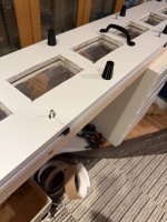
Then there's the upper board. It has the alignment holes but also cut out sections where I can press the foil to the paper:

The ridges have "post it" glue and holds the foil in place so the foil doesn't have to touch the board too much:

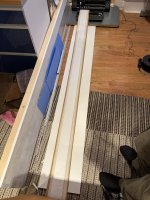
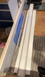
I then flip the board around and place it over the lower board. I've put spacers in between first that are removed one by one:

The handles makes the alignment easier but I must also have supports so it doesn't fall when I apply the foil as the board is upside down.

I then remove the spacers one by one and press the foil onto the paper and remove the upper board.
Care must be taken when releasing the foil from the ridges.

I spray 3M Spraymount onto the aluminium foil, that spray is less stronger than the 77 spray.
A second layer of baking paper is applied:

I tape the edges to secure the layers:

Then it is time to cut...
But it is nice to have something to do indoors when the outdoor temperature is below -15° in the morning and the summer time pool parties are far far away:
Out of two shelf boards 30cm by 246cm I make a jig.
Here's the bottom board with alignment screws:
I use a 15cm wide 100µm aluminium foil as guidance and to keep the surface washable:
I tape down the 15cm wide milk paper, this will be the cutting mat when I later do the cutting with the SC5.
I then spray the 3M 77 glue on the milk paper, the strongest glue that I use, and apply the baking paper:
By the way, both the paper and the aluminium foil that I use are available at any grocery store in Sweden:
Then there's the upper board. It has the alignment holes but also cut out sections where I can press the foil to the paper:
The ridges have "post it" glue and holds the foil in place so the foil doesn't have to touch the board too much:
I then flip the board around and place it over the lower board. I've put spacers in between first that are removed one by one:
The handles makes the alignment easier but I must also have supports so it doesn't fall when I apply the foil as the board is upside down.
I then remove the spacers one by one and press the foil onto the paper and remove the upper board.
Care must be taken when releasing the foil from the ridges.
I spray 3M Spraymount onto the aluminium foil, that spray is less stronger than the 77 spray.
A second layer of baking paper is applied:
I tape the edges to secure the layers:
Then it is time to cut...
Attachments
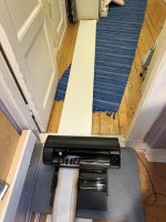
Cutting requires 250cm in front of and behind the SC5:

I use the roller to align the mat into the SC5:

I remove the second layer of baking paper before applying the 3M 77 glue:

Then I weed. The reason for doing the weeding after the glue has been applied is that it is so much easier to remove the finished membrane from the cutting mat.

Next is the BOPP:

It's applied in the same manner as the first aluminium layer:

Then a new spray with the 3M 77 glue and then applying the 6µm aluminium foil with the paper backing:


The membrane is then removed from the cutting mat and trimmed to its correct width:

To remove the paper backing is easy, just a quick dip in water,

rip the paper off and hang up to dry:

Then apply talcum powder to bind any glue residues:

At this stage I don't know how the membrane will sound, but it will for sure smell good!
Complete membrane with 220cm efficient length weighs 10grams:

And has a resistance of 5.7Ω:

The 248cm membrane is 220cm after corrugation if I stretch it a little bit:

And now I have to repeat the procedure in the last couple of post for the rest of the membranes...
I use the roller to align the mat into the SC5:
I remove the second layer of baking paper before applying the 3M 77 glue:
Then I weed. The reason for doing the weeding after the glue has been applied is that it is so much easier to remove the finished membrane from the cutting mat.
Next is the BOPP:
It's applied in the same manner as the first aluminium layer:
Then a new spray with the 3M 77 glue and then applying the 6µm aluminium foil with the paper backing:
The membrane is then removed from the cutting mat and trimmed to its correct width:
To remove the paper backing is easy, just a quick dip in water,
rip the paper off and hang up to dry:
Then apply talcum powder to bind any glue residues:
At this stage I don't know how the membrane will sound, but it will for sure smell good!
Complete membrane with 220cm efficient length weighs 10grams:
And has a resistance of 5.7Ω:
The 248cm membrane is 220cm after corrugation if I stretch it a little bit:
And now I have to repeat the procedure in the last couple of post for the rest of the membranes...
Attachments
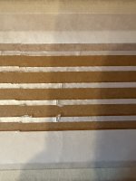
To avoid that the cutting mat moves too much to and fro during cutting; that will for sure get it misaligned, the cutting is divided in 22 parts.
But at every stop/pause, the cutting mat is "released" and can move sideways. So there's a risk for some misalignment:

This is okay for the first set of membranes, but must be solved for the final membranes.
Maybe it is just a matter of having a cutting mat that is cut perfect and has the same width throughout its length.
But at every stop/pause, the cutting mat is "released" and can move sideways. So there's a risk for some misalignment:
This is okay for the first set of membranes, but must be solved for the final membranes.
Maybe it is just a matter of having a cutting mat that is cut perfect and has the same width throughout its length.
Attachments
So it was not so easy to scale the membranes to their full length (220cm).
I need to all start over again, perhaps more "scientific" this time.
One thing that has bothered me is the SPL, especially in the highs.
But doing an RTA measurement with pink noise as input shows that it is not that bad:

For this 6/6µm (6µm traces, PEN, 6µm alu on the back) membrane, the distortion levels are too high though; the corrugation is simply not good enough.
I will now make test membranes with 6/9, 9/9, 9/14, 14/14 and so on to find the lightest membrane with good enough corrugation.
I need to all start over again, perhaps more "scientific" this time.
One thing that has bothered me is the SPL, especially in the highs.
But doing an RTA measurement with pink noise as input shows that it is not that bad:
For this 6/6µm (6µm traces, PEN, 6µm alu on the back) membrane, the distortion levels are too high though; the corrugation is simply not good enough.
I will now make test membranes with 6/9, 9/9, 9/14, 14/14 and so on to find the lightest membrane with good enough corrugation.
A couple of rabbit holes later...
I've managed to bake membranes with the 3M 74 PET film.
I use 40µm aluminium foils with the membrane in the middle like a sandwich.

Then I roll the corrugated membrane onto a steel cylinder:

I then put the steel cylinder with the rolled up sandwich into the oven and bake it at 140°C for 20 minutes.
The corrugated membranes are now a lot stiffer.
Mid membrane with 14µm aluminium:


Usable from 200Hz. Intended use is 300Hz to 2-3kHz.
Tweeter membrane with 6µm aluminium:

With PEQ applied, the SPL will do, at least for me.

2HD at -70dB and higher order HDs at -80dB! Intended use is from 2-3kHz.
I must remember to remove the plastic insert before I place the cylinder in the oven!

I've managed to bake membranes with the 3M 74 PET film.
I use 40µm aluminium foils with the membrane in the middle like a sandwich.
Then I roll the corrugated membrane onto a steel cylinder:
I then put the steel cylinder with the rolled up sandwich into the oven and bake it at 140°C for 20 minutes.
The corrugated membranes are now a lot stiffer.
Mid membrane with 14µm aluminium:
Usable from 200Hz. Intended use is 300Hz to 2-3kHz.
Tweeter membrane with 6µm aluminium:
With PEQ applied, the SPL will do, at least for me.
2HD at -70dB and higher order HDs at -80dB! Intended use is from 2-3kHz.
I must remember to remove the plastic insert before I place the cylinder in the oven!
I'm not to happy with the frequency response for the tweeter above 10kHz; I need to make the -10dB/octave slope less steep

I can equalize below 10kHz but I cannot raise the output as it will lead to distortion in the digital realm.
Looking at the Helmholtz resonator frequency:

one solution is to raise the Helmholtz resonator frequency by either make the opening larger or make the volume or depth smaller.
The opening cannot be any larger, so it'll have to be the other two.
I've been in this rabbit hole before using inserts for the tweeter:

So the gaps between the opening were filled and a 0.5mm layer is added to the top of the magnets thus reducing the volume.
This was unsuccessful as the distortion was too high.
Probably due to the corrugated membrane touched the insert.
But what if I make the tweeter membrane less corrugated?
And perhaps, as OllBoll has concluded, also change the surround material.
I can equalize below 10kHz but I cannot raise the output as it will lead to distortion in the digital realm.
Looking at the Helmholtz resonator frequency:
one solution is to raise the Helmholtz resonator frequency by either make the opening larger or make the volume or depth smaller.
The opening cannot be any larger, so it'll have to be the other two.
I've been in this rabbit hole before using inserts for the tweeter:
So the gaps between the opening were filled and a 0.5mm layer is added to the top of the magnets thus reducing the volume.
This was unsuccessful as the distortion was too high.
Probably due to the corrugated membrane touched the insert.
But what if I make the tweeter membrane less corrugated?
And perhaps, as OllBoll has concluded, also change the surround material.
And perhaps, as OllBoll has concluded, also change the surround material.
Since you have a dedicated midrange and a tweeter, I think you can get the best suspension for each driver by using the EPDM rubber for the midrange and soft foam for the tweeter.
Less corrugation will give you more driving force/mass which is the problem. The mass is too high. If the mass was zero you would have an infinite response (straight forward)
Sorry, with less corrugation I meant less "amplitud" but higher "frequency". Then the driving force/mass ratio should be same?
The 2.4m long and 23mm wide tweeter membrane weighs 3.2 grams. It has aluminium fillers between the conductive traces.

With the now successful baking, the PET without fillers might withhold the corrugation by its own:

To support the corrugation, I also have return conductive traces outside the magnets where the magnetic flow density is about half.
But those return traces runs where the surround is. The idea is that these outer traces should help the whole membrane to move; making the membrane breakup happen at higher frequencies.
With the now successful baking, the PET film with only the center trace might withhold the corrugation by its own:

I will tests this. And also re-test the foam as surround. And the tweeter Helmholtz insert. And ...

Thank you very much, esl63😉.
The 2.4m long and 23mm wide tweeter membrane weighs 3.2 grams. It has aluminium fillers between the conductive traces.
With the now successful baking, the PET without fillers might withhold the corrugation by its own:
To support the corrugation, I also have return conductive traces outside the magnets where the magnetic flow density is about half.
But those return traces runs where the surround is. The idea is that these outer traces should help the whole membrane to move; making the membrane breakup happen at higher frequencies.
With the now successful baking, the PET film with only the center trace might withhold the corrugation by its own:
I will tests this. And also re-test the foam as surround. And the tweeter Helmholtz insert. And ...
Thank you very much, esl63😉.
- Home
- Loudspeakers
- Planars & Exotics
- Yet another Planar Magnetic Line Source, the SMAPPP