Well I must say Cogeniac, I have just been taught more on these amps in 8 pages than I have from reading for TWO YEARS. The way you just went through the section by section of operation AND explained it is just amazing.
I am on limited time at the moment but I owe you to no end, that was fantastic.
Trying to ask what you just gave is almost impossible. I will talk and repay you in the future, the short around the corner future.
Just excellent.
Thanks.
I am on limited time at the moment but I owe you to no end, that was fantastic.
Trying to ask what you just gave is almost impossible. I will talk and repay you in the future, the short around the corner future.
Just excellent.
Thanks.
I spent a little more time with this amp today. after having everything in balance last night, I fired it up today and found it was again out of balance. Part of this was an obviously bad Q110 (probably stressed from the other issues prior to getting it all to work).
However, after trying to get it balance on its own, I resorted to putting in a pot at R144 (this is the resistor that sets the current source for the positive side diff pair. Note that yesterday my issue was the negative side overpowering the positive side. Today it was the opposite.
I thought for a while that maybe I had another bad transistor. To test this I jumpered a 6.8K resistor across R106 (the 1K load resistor on the Diff pair). this resistance value sets the voltage for Q111, and therefore sets the bias current for the Q109 and Q111 stack (the high gain driver stage).
By connecting and disconnecting this resistor I was able to shift the bias level at the input to Q109, and doing this I could see the collector voltage on Q111 change, so it was clear the transistors were alive.. Seeing this, and testing this on the negative side (R107, Q110, and Q112). Same behavior..
So, I finally put a 1K pot in place of R144, and fired it back up. Sure enough, by adjusting this pot I was able to completely null out the output offset!! As noted in one of my earlier posts, the net voltage changes from this at the Diff pair emitters was very small (a few tens of millivolts)...
I then checked the gain on both the positive and negative sides of the system. They look exactly the same (which they should since the gain is fixed by several precision resistors).
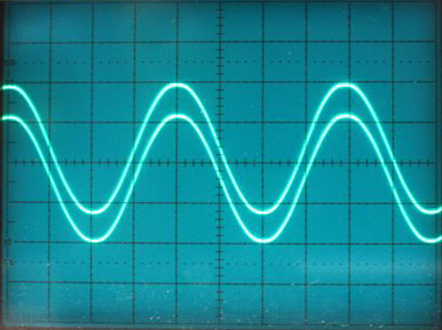
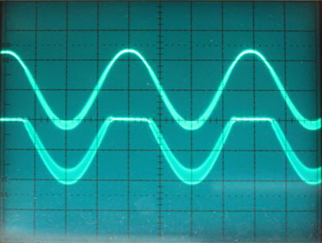
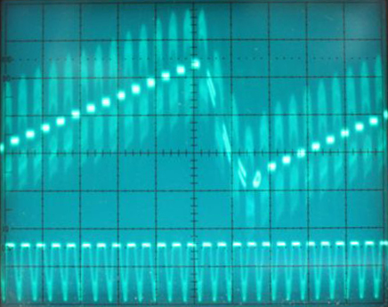
Here are the signals at terminals 3 and 4 of the board. I put a 680 ohm load across this point to emulate the input load presented by the output stages. This is at 20 volts per division, so you can see that each signal is running between 0 and +/-80 volts, This is the highest I can drive it without it clipping.
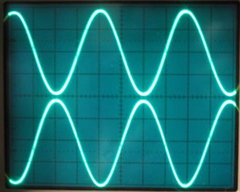
As you can see, the positive side signal starts at about 1.5 volts and goes to about 80 volts. and the negative side signal starts at about -1.5 volts and goes to -80 volts.
I see two serious issues with this image. First, each signal should be cutting off over about 1/2 the cycle. Otherwise each side is essentially operating in Class A.
More importantly, the fact that the two signals are 180 degrees out of phase seems odd since this puts the voltage peaks at the same time instead of anti phase. This explains why the amplifier has a huge hum from the transformer, since at the peaks it is basically passing current through BOTH output banks, and at the zero signal points both banks are cut off. Essentially in this mode the amplifier is a huge heater, but it delivers no power to the load...
What we really want to see here is the following signal set:
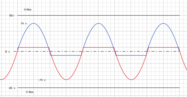
So the signals should actually be in phase, and they should be 2X this signal level, only each one should represent only one half cycle. So the positive side should go from about -1.5 to +80, when the negative side is clipped at about 1.5 volts, and then the negative side should got from +1.5 to +80 while the positive side is at -1.5 volts.. At least that's how an AB amp is supposed to work...
I'll do more sleuthing tomorrow on this now that I have my new scope!
Cheers.
Scott
Her
However, after trying to get it balance on its own, I resorted to putting in a pot at R144 (this is the resistor that sets the current source for the positive side diff pair. Note that yesterday my issue was the negative side overpowering the positive side. Today it was the opposite.
I thought for a while that maybe I had another bad transistor. To test this I jumpered a 6.8K resistor across R106 (the 1K load resistor on the Diff pair). this resistance value sets the voltage for Q111, and therefore sets the bias current for the Q109 and Q111 stack (the high gain driver stage).
By connecting and disconnecting this resistor I was able to shift the bias level at the input to Q109, and doing this I could see the collector voltage on Q111 change, so it was clear the transistors were alive.. Seeing this, and testing this on the negative side (R107, Q110, and Q112). Same behavior..
So, I finally put a 1K pot in place of R144, and fired it back up. Sure enough, by adjusting this pot I was able to completely null out the output offset!! As noted in one of my earlier posts, the net voltage changes from this at the Diff pair emitters was very small (a few tens of millivolts)...
I then checked the gain on both the positive and negative sides of the system. They look exactly the same (which they should since the gain is fixed by several precision resistors).
Here are the signals at terminals 3 and 4 of the board. I put a 680 ohm load across this point to emulate the input load presented by the output stages. This is at 20 volts per division, so you can see that each signal is running between 0 and +/-80 volts, This is the highest I can drive it without it clipping.
As you can see, the positive side signal starts at about 1.5 volts and goes to about 80 volts. and the negative side signal starts at about -1.5 volts and goes to -80 volts.
I see two serious issues with this image. First, each signal should be cutting off over about 1/2 the cycle. Otherwise each side is essentially operating in Class A.
More importantly, the fact that the two signals are 180 degrees out of phase seems odd since this puts the voltage peaks at the same time instead of anti phase. This explains why the amplifier has a huge hum from the transformer, since at the peaks it is basically passing current through BOTH output banks, and at the zero signal points both banks are cut off. Essentially in this mode the amplifier is a huge heater, but it delivers no power to the load...
What we really want to see here is the following signal set:
So the signals should actually be in phase, and they should be 2X this signal level, only each one should represent only one half cycle. So the positive side should go from about -1.5 to +80, when the negative side is clipped at about 1.5 volts, and then the negative side should got from +1.5 to +80 while the positive side is at -1.5 volts.. At least that's how an AB amp is supposed to work...
I'll do more sleuthing tomorrow on this now that I have my new scope!
Cheers.
Scott
Her
Last edited:
Thanks 1edsauto. It's nice to know others are reading, and benefitting from this.Well I must say Cogeniac, I have just been taught more on these amps in 8 pages than I have from reading for TWO YEARS. The way you just went through the section by section of operation AND explained it is just amazing.
I am on limited time at the moment but I owe you to no end, that was fantastic.
Trying to ask what you just gave is almost impossible. I will talk and repay you in the future, the short around the corner future.
Just excellent.
Thanks.
SO far, I have been trying to figure out how this sucker is supposed to work, so I can get it working properly! I am an EE, but it has been 30 years or so since I dug into actual component by component circuit design.
It's bit like doing a crossword puzzle. The designer know what he was trying to accomplish, but all that is hidden from us except by the schematic...so I have been trying to re-discover what is what...
I think, once I have this working, I may develop an online tutorial on this amp, since it is so interesting...sort of what I am doing here - a step by step walkthrough of how each section is supped to work, and how it interacts with the other sections - but not as exploratory.
I have also discovered several useful tricks to isolate the sections of the amp so I can be sure one part is working before moving to the next. SO I'll include those.
Given that we have no significant production cost constraints today, I am seriously considering reworking a portion of this amplifier so it is more stable and less prone to DC offset issues. I have some rather expensive speakers that would not take well to large DC currents... So, while I like this amplifier, I am reluctant to use it in my system as designed. A simple component failure could ruin half my system, and the servo and fuses are not going to prevent that.
For starts, I think a self balancing dual current source for the input stage would be a very useful improvement. Something that can assure perfect bias balance and also allow the user to trim the AB bias point for the output. The output bias circuit is also a real kludge. This is the mess of resistors and the Q201 and 301 transistors between the driver stacks (Q110/Q112 and Q110/Q111) and the output boards.
They use transistors physically glued into the heatsinks in an attempt to create thermally compensating bias network to link the output stage to the driver stage. It is as clear a mud how that is supposed to work..
Meanwhile, I'll keep plodding forward.
Scott
Here is an interesting diagram I generated based on the Class AB concept. It shows that the inputs to the output stages need to be IN PHASE. If they aren't then the amplifier will simply push current back and forth internally, and the potential on the load (i.e. the speaker) will be essentially zero at all times.
In practice the Class A region is actually pretty small. I have exaggerated it here to illustrate the idea.
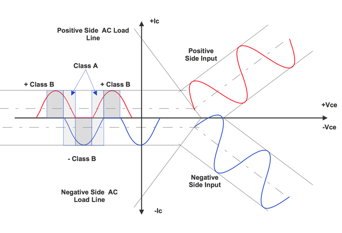
Scott
In practice the Class A region is actually pretty small. I have exaggerated it here to illustrate the idea.
Scott
Last edited:
Now that I have the bias stuff squared away, I decided to have a look at what the waveforms are supposed to look like in the various parts of the amplifier.
Here is how I think they should look. Remember the service manual says that the control board gain stages are Class A. So taking that to heart, I am assuming that the Q109/Q111 and Q110/Q112 stages are biased to just turn on at zero input, and reach max current art max input wight he zero point somewhere in the middle (i.e. Class A).
Things get a little odd at the output, which I have simplified here to just resistor network, with zero current gain, since, as a current amplifier with push and pull stages, you really need to look at how the drivers are going to affect the currents through the load.
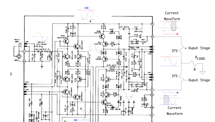
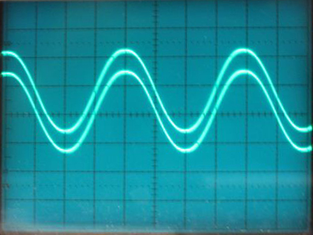
This morning I checked out the amp again with the setup as shown in the diagram above. As I suspected lying in bed this AM, I found that one channel of my new scope was on "invert".. so the waveform shown a couple of posts above is incorrect. Here is what the voltage signals at the "output resistors" looks like.
Zero volts is the middle of the display. This is at 5 volts/division.
And here is how these waveforms look tweaking the current source pot. As you can see the pot causes the displacement of the two waveforms up and down relative to the zero crossing, thereby adjusting the Class AB bias points. Because these circuits are linked by the output bias control network (that messy Q201/Q301 kludge) the two signals both change when the bias on one is adjusted. Using two pots (one on each current source), I will be able to adjust both the overall bias level AND the relative bias offsets, so then I can be sure the system is optimally set up.
I think the very best solution to the bias issue for these amps is a self compensating dual current source. The existing setup uses two separate current sources that depend on component values and the DC servo to keep things properly aligned. If I can put in a dual current source that is designed to assure that the currents are equal (so a constant EQUAL current source), then the servo can deal with very minor variations and thermal changes elsewhere in the overall circuit to maintain balance. That should be pretty easy to design..
I think I am going to work this out after the amp is fully functioning, and then make a new upgraded control board based on this.
Cheers.
Scott
Here is how I think they should look. Remember the service manual says that the control board gain stages are Class A. So taking that to heart, I am assuming that the Q109/Q111 and Q110/Q112 stages are biased to just turn on at zero input, and reach max current art max input wight he zero point somewhere in the middle (i.e. Class A).
Things get a little odd at the output, which I have simplified here to just resistor network, with zero current gain, since, as a current amplifier with push and pull stages, you really need to look at how the drivers are going to affect the currents through the load.
This morning I checked out the amp again with the setup as shown in the diagram above. As I suspected lying in bed this AM, I found that one channel of my new scope was on "invert".. so the waveform shown a couple of posts above is incorrect. Here is what the voltage signals at the "output resistors" looks like.
Zero volts is the middle of the display. This is at 5 volts/division.
And here is how these waveforms look tweaking the current source pot. As you can see the pot causes the displacement of the two waveforms up and down relative to the zero crossing, thereby adjusting the Class AB bias points. Because these circuits are linked by the output bias control network (that messy Q201/Q301 kludge) the two signals both change when the bias on one is adjusted. Using two pots (one on each current source), I will be able to adjust both the overall bias level AND the relative bias offsets, so then I can be sure the system is optimally set up.
I think the very best solution to the bias issue for these amps is a self compensating dual current source. The existing setup uses two separate current sources that depend on component values and the DC servo to keep things properly aligned. If I can put in a dual current source that is designed to assure that the currents are equal (so a constant EQUAL current source), then the servo can deal with very minor variations and thermal changes elsewhere in the overall circuit to maintain balance. That should be pretty easy to design..
I think I am going to work this out after the amp is fully functioning, and then make a new upgraded control board based on this.
Cheers.
Scott
Last edited:
OK, so today I spent a few hours fiddling with the output stage.
There are no obvious shorts, so that's good.
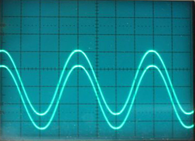
I tried applying one control board output to the output board. The first observation is that since there are only positive and negative side currents at the output, you MUST have a load on the output. I had earlier gotten a big 350 watt wire would 8 ohm resistor...
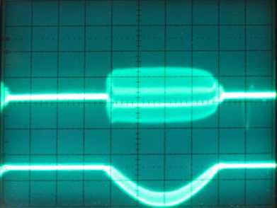
so I hooked that up, and got the following result. This has the correct waveform shape, but there is obviously some oscillation...The upper trace is the output of the control board, and the lower trace is the output of the amplifier into an 8 Ohm load (it is a big 350 watt sucker!!).
I then hooked up the other side..and found it was the same. However, when I hook both sides up together, I get a single full wave form , but with a significant oscillation...
This gets MUCH worse when I connect the feedback line...
So now I need to figure what what is causing this oscillation...
There are no obvious shorts, so that's good.
I tried applying one control board output to the output board. The first observation is that since there are only positive and negative side currents at the output, you MUST have a load on the output. I had earlier gotten a big 350 watt wire would 8 ohm resistor...
so I hooked that up, and got the following result. This has the correct waveform shape, but there is obviously some oscillation...The upper trace is the output of the control board, and the lower trace is the output of the amplifier into an 8 Ohm load (it is a big 350 watt sucker!!).
I then hooked up the other side..and found it was the same. However, when I hook both sides up together, I get a single full wave form , but with a significant oscillation...
This gets MUCH worse when I connect the feedback line...
So now I need to figure what what is causing this oscillation...
Last edited:
I can only echo this,you have a talent there Scott, keep up the good workWell I must say Cogeniac, I have just been taught more on these amps in 8 pages than I have from reading for TWO YEARS. The way you just went through the section by section of operation AND explained it is just amazing.
I am on limited time at the moment but I owe you to no end, that was fantastic.
Trying to ask what you just gave is almost impossible. I will talk and repay you in the future, the short around the corner future.
Just excellent.
Thanks.
Many thanks
Thanks tisp!
Given that this oscillation only occurs when the power stages are connected, and given that it gets worse when the feedback loop is closed, I think I can conclude that it is originating in the power stage. Also, since it is present on either side of the system (positive and negative) independently, I am thinking it may be a power supply issue.
What I can't figure out is why it would cause so much heating in the output stages. When I connect both sides the lights in my lab dim (yes, literally!), and you can feel the heatsinks warming up....I suppose it is possible that the oscillation is somehow out of phase between the two sides, and that is causing the transistors on both sides to come on at the same time. That would certainly cause this sort of power drain...
As I noted a couple of posts above, if both sides of the power stages are on at the same time, they will just pass current from one to the other. The load will just sort of watch this current go by, but, since the potential at the load will be essentially zero, very little of this current will pass through the load.
Here is the hypothesis in a diagram..
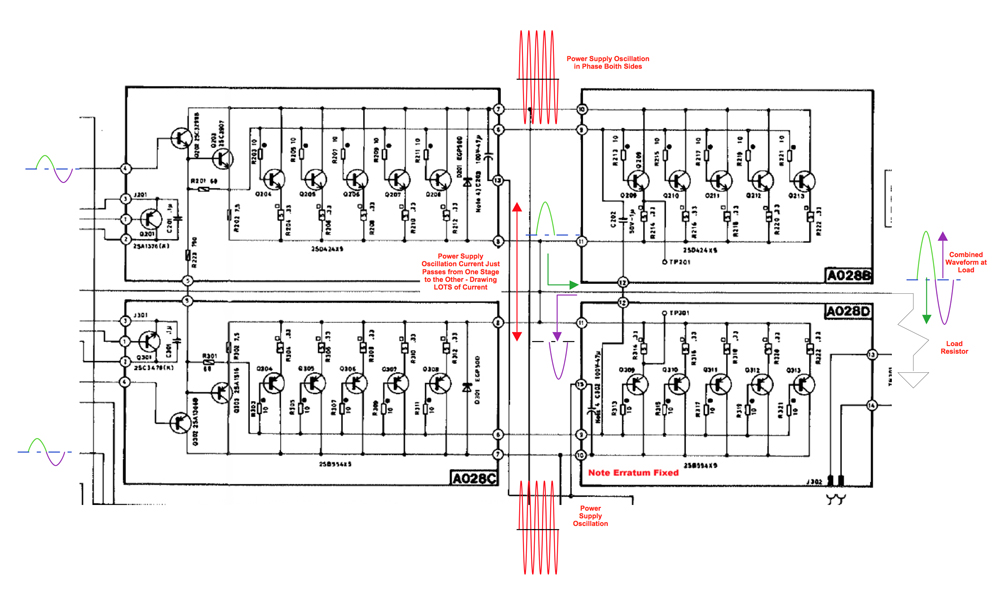
The audio input signal is shown in green and purple. When the green half cycle occurs, the positive side of the output stage conducts, Since the negative side is reverse biased at this point, it is not conducting (ignoring the oscillation), so the positive current flows to the load, causing the voltage to rise at the load. On the negative half cycle (shown in purple), the positive side is back biased and the negatives die conducts current the other way, causing the voltage at the load to swing the opposite direction. This is the classic "push pull " operation.
Now, if we introduce an oscillation in the power supply, AND if this oscillation is out of phase, so the negative side is swinging more negative when the positive side is swinging more positive, and IF (this is the big IF) this instability somehow manages to bias on the other output board, then we will get conduction through both boards at the same time, and so the oscillation will also draw lots of current.
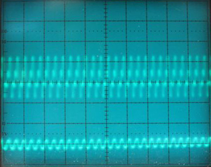
I took a look at the supply rails (at the big caps) with only the negative side conducting.
Here is the positive rail (top) at 50 mV per division.. You can see that when the negative side is conducting, it is oscillating at some very high frequency, and this oscillation also shows up on the supply rail.
I then zoomed in on this, and found that the negative supply rail has a variety of bad juju.. The photo is a bit blurry because there is so much hash that the scope had a hard time syncing.. But you can see there are at least two major oscillations on the supply rail. One is very high frequency, and the other is much lower. The lower sawtooth frequency is 20 times lower than the 1KHz audio signal, so it is going at about 60 Hz. That is almost assuredly AC ripple.. which isn't great, but is probably not my core problem.
The higher frequency oscillations are much higher. Here is a zoom of those..
I didn't try to measure the frequency of these, but they are very high, probably well over 100 KHz...The lower trace is the main output signal (a tiny slice of it in time, which is why it looks relatively flat). The upper trace is the supply line. It has the same high frequency oscillation as the output signal, plus some even higher components.
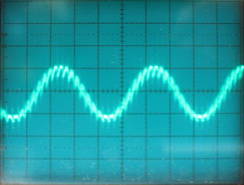
When I attach the other driver signal, I get the full audio waveform, but it has a substantial additional oscillation. This appears to be about 18 times the frequency of the audio signal, so about 18 KHz.
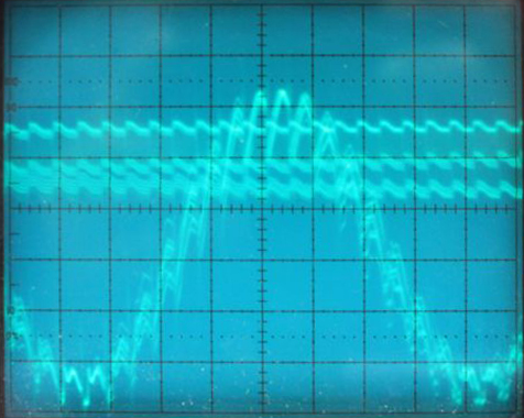
If you look closely at this image, you will see that, while I still have the higher and lower frequency oscillations (the zigzag lines on the power supply rail are just that 60 Hz sawtooth walking past the synced 1 KHz audio signal), but I also have this 18KHz signal which not only has the basic 18 KHz messy signal, but it also has some huge spikes (these are difficult to see because they are very short. I believe these are what is causing the conduction between the stages, and the high current draw. Fortunately they are very fast, or I'd probably have smoked the output stages. Even here I only connected the other side long enough to take the photo..
I am wondering if perhaps my big filter caps, or the main rectifier bridge are producing this..
Given that this oscillation only occurs when the power stages are connected, and given that it gets worse when the feedback loop is closed, I think I can conclude that it is originating in the power stage. Also, since it is present on either side of the system (positive and negative) independently, I am thinking it may be a power supply issue.
What I can't figure out is why it would cause so much heating in the output stages. When I connect both sides the lights in my lab dim (yes, literally!), and you can feel the heatsinks warming up....I suppose it is possible that the oscillation is somehow out of phase between the two sides, and that is causing the transistors on both sides to come on at the same time. That would certainly cause this sort of power drain...
As I noted a couple of posts above, if both sides of the power stages are on at the same time, they will just pass current from one to the other. The load will just sort of watch this current go by, but, since the potential at the load will be essentially zero, very little of this current will pass through the load.
Here is the hypothesis in a diagram..
The audio input signal is shown in green and purple. When the green half cycle occurs, the positive side of the output stage conducts, Since the negative side is reverse biased at this point, it is not conducting (ignoring the oscillation), so the positive current flows to the load, causing the voltage to rise at the load. On the negative half cycle (shown in purple), the positive side is back biased and the negatives die conducts current the other way, causing the voltage at the load to swing the opposite direction. This is the classic "push pull " operation.
Now, if we introduce an oscillation in the power supply, AND if this oscillation is out of phase, so the negative side is swinging more negative when the positive side is swinging more positive, and IF (this is the big IF) this instability somehow manages to bias on the other output board, then we will get conduction through both boards at the same time, and so the oscillation will also draw lots of current.
I took a look at the supply rails (at the big caps) with only the negative side conducting.
Here is the positive rail (top) at 50 mV per division.. You can see that when the negative side is conducting, it is oscillating at some very high frequency, and this oscillation also shows up on the supply rail.
I then zoomed in on this, and found that the negative supply rail has a variety of bad juju.. The photo is a bit blurry because there is so much hash that the scope had a hard time syncing.. But you can see there are at least two major oscillations on the supply rail. One is very high frequency, and the other is much lower. The lower sawtooth frequency is 20 times lower than the 1KHz audio signal, so it is going at about 60 Hz. That is almost assuredly AC ripple.. which isn't great, but is probably not my core problem.
The higher frequency oscillations are much higher. Here is a zoom of those..
I didn't try to measure the frequency of these, but they are very high, probably well over 100 KHz...The lower trace is the main output signal (a tiny slice of it in time, which is why it looks relatively flat). The upper trace is the supply line. It has the same high frequency oscillation as the output signal, plus some even higher components.
When I attach the other driver signal, I get the full audio waveform, but it has a substantial additional oscillation. This appears to be about 18 times the frequency of the audio signal, so about 18 KHz.
If you look closely at this image, you will see that, while I still have the higher and lower frequency oscillations (the zigzag lines on the power supply rail are just that 60 Hz sawtooth walking past the synced 1 KHz audio signal), but I also have this 18KHz signal which not only has the basic 18 KHz messy signal, but it also has some huge spikes (these are difficult to see because they are very short. I believe these are what is causing the conduction between the stages, and the high current draw. Fortunately they are very fast, or I'd probably have smoked the output stages. Even here I only connected the other side long enough to take the photo..
I am wondering if perhaps my big filter caps, or the main rectifier bridge are producing this..
Last edited:
AH HA!!!!
http://www.hagtech.com/pdf/snubber.pdf
Interesting article that talks about rectifier diode ringing and "snubber circuits...
I suspect the bridge in my amp is failing and the diodes are failing to turn off effectively or quickly enough, and are ringing under heavy load.. 7.
I have some new filter caps, so I am going to try replacing those first, but I suspect I need a new bridge..
Scott
Hi Scott,
The heat sinks must be grounded, or you will get what you are seeing there.
-Chris
OK, I tried that. It doesn't seem to have much effect, and clearly this is not the cause of the high current draw when both sides of the driver board are connected to the outputs. Fixing up the input signal grounds did clean up the really high frequency fuzz I had in the photos above.. but the current draw remains. I am thinking the rectifier may have too much internal resistance, so when the outputs start drawing current it draws down the supply rail, causing the bias points to change and resulting in both sides conducting.
The power supply is clearly noisy when the signals are applied the the output, so I am going to replace the filter caps, and the rectifier. The caps are original, and I bought a set when I started this project. The rectifier is cheap. I upped the current capacity of the bridge to 50 Amps, just for good measure..
I did uninteresting experiment on this amplifier. First, I added the trim pots to the current sources, so I can tune those very accurately. Doing this, I found that when both outputs are connected the amplifier works OK as longs I dial down the current flow in the diff pairs. This basically cuts down the drive current on the driver stages, which in turn clips the outputs at normal input signal levels. As I turn the current up, the clipping goes away, but the heat and the hum from the transformer come back, and the output waveform has oscillations on it.
I then tried a different experiment. I disconnected the load transistors for the diff pairs, and put in a resistor network consisting of a 100K trim pot and a 22K resistor. this allowed me to manually control the DC signal level at the init to the driver stages (Q109/Q110). I then measured the output voltage across an 8 ohm load.
I can run the DC signal at the output from zero to +/-67 volts by turning the trimmers. However, when I get above about 30 volts, the transformer starts to hum again.
I put the scope on the DC rail, and found that there is a low frequency sawtooth wave on the DC supply. As I raise the output voltage level the amplitude of this sawtooth rises.
At about 40 volts output, the sawtooth is about 0.6 volts peak to peak, and the hum is reasonably loud.
I have already changed out the big power supply filter caps, so I think this may be a rectifier issue. I'll report back as soon as my new rectifier arrives.
Cheers,
Scott
IT LIVES!!! (well.. almost...)
When I last posted, I was having issues with the buzzing noise from the transformer whenever I connected both sides of the output section. I finally decided that this had to be the bridge rectifier. It turned out it was. It had a lot of ripple and oscillations under load...and I think it was somehow impacting the power transformer under load.
I replaced the bridge with a nice 50 Amp version, and the amp fired right up (OK, that was after I discovered that the 20 watt resistor on the soft start bad was bad, and while fixing that found that the caps on that board had leaked as well...). The air intake cleaner juice I have been using (some pretty macho hydrocarbons...) removed the gunk pronto.. Good to know!
So now I get good signal at the output, no significant external noise from the transformer, etc. I had some high frequency noise , but I noticed this was on the input signal well before it gets to the amplifier (via a 10:1 voltage divider).. so I put a .01 uF cap across the function generator output and killed that.
The problem I now have is that it all works fine, except, if I connect the feedback line, I kill the output. So, I'll need to troubleshoot that.
Having the input bias controls on those nice multi turn foil trim pots is really nice!!
Whew.. almost done...Been a long road!
In the meantime I managed to score another GFA 565 in better condition. It has been in storage for 15 years, and not fired up, so I'll change out the caps preemptively before I try it out.
Scott
Last edited:
I think the LT1012 op amp is dead. Probably killed by the various shenanigans on the control board. I have ordered some replacements, and will give that a try.
Looking at the schematic, if the output is not perfectly balanced, and the op amp is not working, connecting up the feedback line will drive the negative inputs of the two input diff amps in one direction, presumably biasing the driver stages either off, or all the way on.
With the amp running, but the feedback line disconnected, I measures 0 volts on one input, and about 6 mV on the other. The output was drifting around 3-4 volts (very unstable). So, I think the output is open and I am seeing the offset and thermal drift of the current sources, amplified by the input diff amps. If the output were active, I doubt I'd be seeing it wander around like that...
So, I am pretty sure that is my current problem. Hopefully that will be the last of them!
Scott
Last edited:
Hi scott
Good progress
I think the opamp is an op97,thats the replacement that Walt Jung, one of designers of the amp suggested some years back in this forum.
Good progress
I think the opamp is an op97,thats the replacement that Walt Jung, one of designers of the amp suggested some years back in this forum.
Yeah, I read that. I ordered the OP97 from Mouser an the LT1012 from Digkey. We'll see which one gets here first!
Well, I spent a little more time on the Adcom. Still not working right. I put in the OP97 chip, and hooked up the feedback line and nada. The output was oscillating at some super high frequency and the sine wave input was not present at the output.
The output of the op amp was pinned at 13 volts. The two inputs were at zero and 7 mV...
I also found that with the op amp out of the circuit, and the feedback line disconnected, I can get it to work.
What I have found is that with the current sources set using the 499 ohm resistors, the output is railed positive. If I adjust the resistance of the negative current source (which runs the positive side diff pair), then I can adjust the output so that I get a sine wave around zero volts.
What this tells me is that there is still something significantly out of whack on the control board. Basically the positive side of the board is biased too high, causing the driver (Q111) to be biased on too much. I can dial this back to get the proper output, but when I do that, the servo is then out of whack, since the positive and negative diff pairs are biased differently (the servo presumably assumes they are biased the same...).
So, this tail chasing is not going to work. I guess I need to go back and work out why, with the bias currents set the same, I end up with Q111 turned on too hard.
I tried to edit the last post, but didn't get to it in time. Here is the revised post...
Well, I spent a little more time on the Adcom. Still not working right. I put in the OP97 chip, and hooked up the feedback line and nada. The output was oscillating at some super high frequency and the sine wave input was not present at the output.
The output of the op amp was pinned at 13 volts. The two inputs were at zero and 7 mV...
I also found that with the op amp out of the circuit, and the feedback line disconnected, I can get it to work.
Curiously, with the current sources set using the 499 ohm resistors, the output is railed positive. If I adjust the resistance of the negative current source (which runs the positive side diff pair), then I can adjust the output so that I get a sine wave around zero volts. AT this stage, the current through the 1K loads for the diff pairs is about 1.4 mA...which seems right.
When I do this, I end up with nearly exactly the same voltage drop at each of the 1K load resistors (equal to a few tens of mV..which, across a 1 K resistor means the currents are equal to a few hundred micro amps)..so that's good, although one wonders why the current sources would not be matched properly with equal resistors. I will sort that out later. For now, if the currents are the same, then the diff pairs are operating the same, and this should mean that the output of the control board is correct. Looking at the output signals form the board, then are each just slightly offset from zero, which makes sense for the Class AB operating point.
Interestingly, the high current draw at zero input is back, so this means that I need both of the adjustable current source resistors in place so I can tune the offsets back to the point where I get true AB and not dual semi class A (or whatever we would call the situation when both output banks are on at the same time. ). I can easily do that, and fine tune this. However, the problem with the servo and the feedback remains.
I put the other adjustable current source resistor in place, and found that I can eliminate the high current draw by dialing both current sources back.. not by much.. At about 1.2 mA in each diff pair, the output stages are heavily conducting (blew a circuit breaker!!!).. If I dial this back to about 1 mA there is no noise and little heat, but I see some crossover distortion in the output. At about 1.1 mA, I get a pretty clean waveform, but no heavy current draw, so that seems to be the sweet spot. Using the adjustable pots, it is really easy to get the currents exactly the same (just measure the drop across the 1K load resistors...). The pots have about 20 turns, so the adjustment is very fine. It goes from 240 Ohms to 1.24K.
Once I had the proper current level, I balanced them by removing the input signal, and adjusting the pots until I got zero output offset, and both current sources were at approximately 1.1 mA. AT this stage the output offset drifts around by a few hundred mV in either direction.. something the servo should be able to easily compensate for.
I messed around with the feedback this time too. I found that for some reason the level of feedback is WAY too high. For example, if I simply touch the feedback line to the board at terminal 7, I kill the output (down from +/- 75 volts to about 2 volts, with all sorts of oscillations. OTOH, if I touch the feedback line and also touch a resistor lead to terminal 7, (about 2-3 megohms, through me), the waveform crisps up, and drops by about 5 volts (so a few dB).
I think the feedback network has some issues.
As I see it, the feedback comes in on terminal 7, and goes into the complicated little network around the output of IC 101. I noticed that there is a pair of back to back parallel diodes (D109/D110) that basically shunt this signal to ground through a 1 K resistor, and this little assembly is in parallel with another 1K resistor. The result should be about a 44:1 signal reduction. I am wondering if the resistor values are off, or if the diodes are open. If this was the case, we would-be getting less attenuation in the feedback signal, and it would then overwhelm the input stage. I suppose it is possible that the huge issues with railed 85 volt output voltages the diodes might have opened, and/or the shunt resistor might have opened. That would reduce the feedback attenuation, and cause this overly aggressive feedback situation. In this case too, a DC offset at the output would be amplified by the open loop gain of the servo op amp (which is probably about 20K, causing the op amp output to rail..
So, tomorrow I'll go exploring in this part of the amp..
Cheers,
Scott
OK, so I managed to figure out a few more details of this amplifier, and it seems to be basically working. I am not sure how WELL it is working, but it is generating power in closed loop operation at the right input and output signal levels.
I had been working with only the control board originally, and I had no feedback coming into the board from the output stage. I found that by using two 680 ohm resistors one each between the terminal 3 and 4 locations on the board and ground, I could isolate the positive and negative side driver signals, and more easily troubleshoot the board.
However, this also meant the board was operating open loop. I found I had to turn my signal generator all the way down, and still I had to use a 10:1 divider to keep the driver stages from clipping. Once I connected the feedback, especially with the Op Amp connected, the output went to zero. After some mucking around, I managed to find some setting of the current sources that unhooked the op amp from its power rails, and got the servo working. Basically the servo only works if the output is already pretty closely balanced near zero offset. If there is more than about a volt or two, the servo rails, and this basically shuts off at least one side of the input stage.
So, with all of that working and the feedback wire connected (Terminal 7), I was then able to crank up the input signal level, and voila! For about 2 volts peak to peak (so about 0.7 volts RMS) I get about a 75 volt p-p swing across my big 8 ohm output resistor. I also get a fair bit of heat from this sucker..
My issue now is that I still seem to have some very high frequency oscillations in the amp.
This becomes much more noticeable at low signal levels because the amplitude of the oscillations seems pretty constant. So the lower the input signal level, the greater proportion of the signal is affected by this oscillation.
I'll take some photos of this and post them later tonight. It is difficult to tell if this is some artifact from my signal generator, or if it is actually something generated in the amplifier. It shows up on the two half cycles of the output as almost burst of super high frequency signal, and these bursts show up on the power supply lines as well. It disappears when I turn off the amp but leave to generator on, so I am pretty sure the amp is generating it.
At this stage I think I'll button it up (the control board is sitting in a pano vise on top of the heat sinks), and start tracking down the oscillations...
At least the amp is basically operating correctly now, and it has all of its parts installed, and nothing is burning up or making noise, so that's some progress!
Cheers,
Scott
- Home
- Amplifiers
- Solid State
- Yet Another Adcom GFA-565 Thread