The outputs happen to be triple Darlingtons, which magnifies the errors much!
I have checked the following stage devices and they seem to be working okay, hence my quest for ways to tweak the LTP slightly. Is it advisable to put a trimmer between the emitters, with the wiper going to Q606? Do wise me up, please.
I have checked the following stage devices and they seem to be working okay, hence my quest for ways to tweak the LTP slightly. Is it advisable to put a trimmer between the emitters, with the wiper going to Q606? Do wise me up, please.
This is just a hunch, and I do not have the time to spend fully understanding this new circuit, but it looks like the input diff pair is driven by a current source formed by Q606. The base current is set by the two diodes D606 and D608. The actually current is set by resistor R620. I can see why this circuit woudl have a hard time balancing, since it depends almost entirely on some complicated relationship between R161, 618 and 620. If you increase the tail current flow, by reducing R620, then the DC voltage at the collector of Q602 will go down. If your reduce it, the voltage will go up. So, if you are inclined to install a control element to adjust the nominal offset, then adjusting R620 MAY be one approach.
However, I stand by my observation above, that the amplifier is basically signal ended up to Q614 and Q168, so I suspect even changing the bias point of the diff pair may not affect much.
Can you post more of the right side of the circuit. It looks like the 614 and 618 outputs go to another stage, and that may be more useful in dealing with offsets.
The outputs happen to be triple Darlingtons, which magnifies the errors much!
I have checked the following stage devices and they seem to be working okay, hence my quest for ways to tweak the LTP slightly. Is it advisable to put a trimmer between the emitters, with the wiper going to Q606? Do wise me up, please.
No. The current balance between the diff pair is not going to affect the DC offset. The triple Darlington is a current amplifier, but it will not actually affect the DC offset unless a device is shorted.
This amplifier appears to be Class A (single ended) up to Q614/Q618. After that some how is changes over to Class B, where one end is driven one way and the other the other way, and getting that balance right is the key, both to DC offset and to crossover distortion.
Let's see the output driver section.
Last edited:
Yeah, I don't try to match the PNP and NPN complementaries. Even if they matched at idle, their curves don't track well.
I build a lot of these boards and I get a consistent -3.8 to 4V correction out of the DC servo to bring the amp to 0V.
I build a lot of these boards and I get a consistent -3.8 to 4V correction out of the DC servo to bring the amp to 0V.
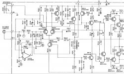

Might help to explain, as much as I understand it, the circuit as it is shown. The differential input pair is a bit like an op amp. The input signal comes in the bas of Q602. Q604 is the non-inverting input. It appears it is there to provide some feedback. The gain of this circuit is roughly set by R616 (which is why a pot there would be bad). The amplified signal comes from the collector of Q602, and goes to the base of Q614. From there it goes out through R648 to some more of the output driver stage (off the schematic). That same signal ALSO goes through capacitor C612, and from there looks like it goes to R650 and off to the negative driver side.
So, up to the output of Q614, there is no positive and negative circuit path, there's only one circuit path. Whatever the bias circuits are for the two transistors (I suspect a 2SC3478 and 2SA1376) is what is going to determine the DC offset. This MAY be affected by the collector voltage at Q614, which may also be affected by Q618 and the circuit with the VR602 pot.
The good news, as I stated earlier, is that unlike the 565, you do not have tons of voltage gain taking small input offsets and amplifying them. The bad news is that this circuit is inherently not very balanced, and so the output stage bias will depend on the bias points of Q164 and the following stages.
Considering adding a fail safe circuit to shut off the amp if the DC offset goes beyond the ability off the DC servo to correct it. Easy way to save $$$K speakers.
Cogeniac, you mentioned in a PM that you were considering adding a comparator to detect if the DC Servo's correction has exceeded +/-10V, and use that to shut off the amp. That should work! I would suggest using the comparator to trip the power relay somehow. It's not enough to disable bias to the front-end. The electrolyte goo could cause a DC offset even if the front-end is off.
But meh, I dunno. I just use Panasonic FC's, a proven formulation, and not worry about it. Those caps are under very little stress. The original leaky Elna's were just a bad formulation.
It is too bad the diff pair was designed to not balance in many Adcom amps. They depend on the servo, and I think that was a mistake. Notice that the servo is only effective for one polarity of unbalance.
Amplifiers that have a balanced diff pair, or complimentary diff pairs work great without a darned DC servo.
Amplifiers that have a balanced diff pair, or complimentary diff pairs work great without a darned DC servo.
@ Phloodpants:
I have put in C1845s for the LTP, and would like to tweak whatever imbalances there are as a result of the not very close match. The moment I disable the DC servo, DC balance swings one way consistently. It is that which I wish to bring closer to zero before activating the servo again. Like I asked earlier, is a trimmer between the emitters of the LTP going to help here?
I have put in C1845s for the LTP, and would like to tweak whatever imbalances there are as a result of the not very close match. The moment I disable the DC servo, DC balance swings one way consistently. It is that which I wish to bring closer to zero before activating the servo again. Like I asked earlier, is a trimmer between the emitters of the LTP going to help here?
Hi The Prof,
Please read my post above.
The diff pair is designed out of balance, the DC servo is required. This is a weak point and it should not have been designed that way.
Please read my post above.
The diff pair is designed out of balance, the DC servo is required. This is a weak point and it should not have been designed that way.
I should clarify... The original leaky caps were the mini-marshmallow-sized brown Elna's marked "Long Life" LOL. They were used for the +/-13.8V supply rails that powers the op-amp and sets a point in the bias string. I use Panasonic FC 47uF/35V. The other one that leaks is the bias spreader cap in the middle of the board. I use Nichicon FG 47uF/100V.
The remaining two electrolytic caps are 100uF local power supply filters, and these are usually just fine. I use Panasonic EE or ED 100uF/160V here.
The remaining two electrolytic caps are 100uF local power supply filters, and these are usually just fine. I use Panasonic EE or ED 100uF/160V here.
@ Anatech:
Sir, can you suggest a way to mod the circuit minimally to make the circuit balance somewhat?
Sir, can you suggest a way to mod the circuit minimally to make the circuit balance somewhat?
The interesting difference between this amp and the 565 is that , since the 565 is full differential Class AB, from start to finish, each side (positive and negative operates independently. So, introducing a small DC offset to the virtual ground between the positive and negative diff pairs allows control of the overall offset.
This Amp is somewhat different. The bias points of the output stages are interdependent, and may vary according to any of the components in the signal chain.
I suggest trying the R620 pot idea. That will allow you to shift the bias point of Q602 up and down, and that should propagate all the way through tot he output stages.
As I suggested, try using a POT for R620. You can use that to turn the bias up or down on Q602, and that will shift the DC voltage at the collector. That shift will propagate through the entire signal path, and should allow you to adjust any offset.
Yeah, I don't get this, but I still wonder if there was some reason for it, besides the servo. The GFA-535 MKI also has this imbalance in the LTP, and it does not have a DC servo. In both designs, the proverbial "Q1" is the more lightly biased. Could it have something to do with the fact that Q1 supplies drive current to the VAS stage?
It is too bad the diff pair was designed to not balance in many Adcom amps. They depend on the servo, and I think that was a mistake. Notice that the servo is only effective for one polarity of unbalance.
Amplifiers that have a balanced diff pair, or complimentary diff pairs work great without a darned DC servo.
Yeah, I don't try to match the PNP and NPN complementaries. Even if they matched at idle, their curves don't track well.
I build a lot of these boards and I get a consistent -3.8 to 4V correction out of the DC servo to bring the amp to 0V.
How are you doing Chris? Saw on your site there were some health issues. Hope all is OK. Did you get my PM?
I think that inherent offset is because the inherent beta of the PNP darlington is lower than the beta of the NPN darlington, so there will always be a slight offset. This is why I have used pots in R144/145, so I can adjust that balance exactly. Using 1% resistors in those spots doesn't help, because the NPN and PNP transistors basally need different resistances/currents to yield the same bias points.
The symmetry of the 565 is beautiful, but it's too bad PNP and NPN transistors are not as symmetric!!
I should clarify... The original leaky caps were the mini-marshmallow-sized brown Elna's marked "Long Life" LOL. They were used for the +/-13.8V supply rails that powers the op-amp and sets a point in the bias string. I use Panasonic FC 47uF/35V. The other one that leaks is the bias spreader cap in the middle of the board. I use Nichicon FG 47uF/100V.
The remaining two electrolytic caps are 100uF local power supply filters, and these are usually just fine. I use Panasonic EE or ED 100uF/160V here.
I have a big digital Tek scope. It stopped working about 18 months ago, and I found that the issue was....Drum roll.. Leaking caps.
These were SMT caps. I think I replaced about 60 of them on that board. Scope works fine now.
Ahh, I love the smell of burning electrolyte..
I was getting repetitive strain injury from the refurbishing work, so that's why I don't do that anymore. Its too much lifting, and wrenching and scrubbing, and just a ridiculous amount of work with how meticulous I get with it. Not real profitable either. I'm doing fairly better since I quit doing that. Now I'm concentrating on board kits and lately, phono preamps.
Cogeniac, you mentioned in a PM that you were considering adding a comparator to detect if the DC Servo's correction has exceeded +/-10V, and use that to shut off the amp. That should work! I would suggest using the comparator to trip the power relay somehow. It's not enough to disable bias to the front-end. The electrolyte goo could cause a DC offset even if the front-end is off.
But meh, I dunno. I just use Panasonic FC's, a proven formulation, and not worry about it. Those caps are under very little stress. The original leaky Elna's were just a bad formulation.
Oh good. So you did get my PM. Yeah, I think triggering the soft start relay using a window comparator sensing the swing on the servo would prevent catastrophic speaker damage and be otherwise invisible. Once I get one of my new boards up and running, I'll experiment with that. Feel free to productize the result!
- Home
- Amplifiers
- Solid State
- Yet Another Adcom GFA-565 Thread