^ Did you read post #1? If not, I'd strongly encourage it. It's very well thought out, IMO. If you actually did read it, here's an important segment you may have overlooked. Emphasis added is mine.
DON'T DO ANY OF THE FOLLOWING, THEY ARE BAD IDEAS
First: I have set the gain of Yes It Can Drive An F4 to 20 volts per volt (+26 dB). An input of 1 volt (peak) produces an output of 20 volts (peak), which is the maximum input signal allowed by an F4. Don't attempt to change the gain unless you really know what you're doing. If you need someone to help you change the gain, that means: you don't really know what you're doing. Stop now.


R.I.P. CrocCap. May your gain now be just where you like it, and the songs even more glorious wherever you are.
(Maybe he will be reincarnated as PacCorc)
I think he mistook the clear and concise reponse incorrectly. He asked a specific question and was kindly and quickly pointed directly to the answer that was also very clear. Probably just had a rough day and mistook the intent, took overly-drastic action.
(Maybe he will be reincarnated as PacCorc)
I think he mistook the clear and concise reponse incorrectly. He asked a specific question and was kindly and quickly pointed directly to the answer that was also very clear. Probably just had a rough day and mistook the intent, took overly-drastic action.
Last edited by a moderator:
Jeez, if I quit every time Jim picks on my choice of elastic driving vinyl rotational device, or every time he tells me to keep it on point and not go on a delicious, fantastic, somewhat orthogonal direction in my comments which do not specify whether the resistor should be 10 or 100 ohms or if it will matter if it's installed backwards (*), comments meant to truly enlighten those who doggedly stick to the point..
I know he tries... but I ignore him. ;-)
Hmm... what was I saying?....
Oh yeah....
Thin skin, I guess.
One comment though, why the choice for 1 V as max input? Many devices will output 2V nowadays. I guess the YITCDAF4 MkII might incorporate a Low/High Gain switch? For 20 or 26 db gain?
Ideally, we want to minimize the overall system gain to minimize noise. Just enough gain to drive everything near the maximum, within the top of their linear behavior... but not much more. A 26 db gain could be a lot and keep the preamp running at a low gain setting... like 10 o'clock?
Or, just drive the F4s with a tube preamp that can put out 20Vrms. It works for me. In many ways, the F4 was means for a tube preamp with their high outputs - mine will do 20Vrms, if you can live with its relatively low power capacity of the F4, it allows the sound of the preamp to come through. It's a very, very, very nice combination.
Although, sometimes I guess you want a true wire with gain... so I guess the Iron Pre is just not enough power to swing it.. you do need the gain between the "normal" source/preamp and the F4. It's a combination I'm after in SE mode. I already got it running on bridged mode. Yowza!! ;-)
One thing, I'm planning on building my YITCDAF4 in a Metal Japanese Cookie Box, so I'm gonna need a power supply. Any ideas? I'm making the bill of materials...
Kit with PC Board and components in... Thanks!
Box, check. Yum... awesome cookies
RCA jacks, need four
Power Supply, likely a Meanwell external brick. What is the required voltage and wattage?
Barrel jacks for power, 1/8th I guess.
Green LED for operation ;~|
Power switch - might incorporate the LED into it?
I don't recall the build instructions...
Stuff the resistors
Stuff the caps, LED, transformer
Tie wrap the two matched transistors
Stuff the transistors and diodes
Wire to jack ( might use a Molex connector )
Do I need to bias it?
What checks should I make before I apply power? Check for DC on the output? Before I plug it into my precious components?
(*) Hmm...does it matter the direction of a resistor? I mean, I know we figure it's bidirectional... but is it? Has anyone tried it? Did Peter Belt ever sell specially treated resistors?
Last edited:
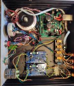
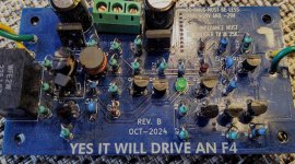
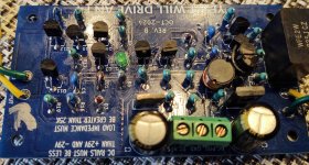
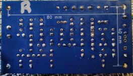
Update on progress. Thanks to the great generosity of Dan (birdbox) I got a replacement BC546C for Q12 that I had installed backwards and fried on my left channel board. Today I replaced Q12 in the correct orientation and did some power on tests using a =/- 24 VDC psu from an existing preamp. No magic smoke this time but the dc offset is not good on either channel. I getting -437mV on the right channel, and 22V on the left (board I smoked Q12 on).
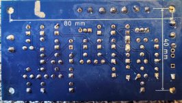
I'm guessing installing Q12 backwards has wrecked more parts, but the I'm no EE so I'm not sure what the cause of the high offset on the right board is. I have attached some pictures. I would greatly appreciate any insights or guidance.
Many Thanks,
Paul
- I have double checked and measured all resistors on both boards, all match schematic.
- Checked all transistors, all are in correct orientation and match the schematic.
- The orientations of ZD1, D2, and D3 match pics posted on this thread.
I'm guessing installing Q12 backwards has wrecked more parts, but the I'm no EE so I'm not sure what the cause of the high offset on the right board is. I have attached some pictures. I would greatly appreciate any insights or guidance.
Many Thanks,
Paul
Attachments

If the LED on the repaired board doesn't glow at the same level of brightness as the LED on the always-worked board, the repaired board has a fatal disease, and the best option is probably to build a brand new replacement board with new PCB and all new components.
If the LEDs glow identically that probably indicates that the supply filters Q1 and Q2 are OK, the master current source Q3-Q4 is okay, and the tail source Q7 is okay. I'd suggest you replace all four of the upper signal PNP transistors Q6, Q8, Q10, and Q11 and cross your fingers that one of them was the culprit. However if it's just as expensive or time consuming to buy a brand new group-buy 1-board kit, as to buy these transistors, then absolutely replace everything. Now you're very sure you've put the bad part(s) into the trash can.
If the LEDs glow identically that probably indicates that the supply filters Q1 and Q2 are OK, the master current source Q3-Q4 is okay, and the tail source Q7 is okay. I'd suggest you replace all four of the upper signal PNP transistors Q6, Q8, Q10, and Q11 and cross your fingers that one of them was the culprit. However if it's just as expensive or time consuming to buy a brand new group-buy 1-board kit, as to buy these transistors, then absolutely replace everything. Now you're very sure you've put the bad part(s) into the trash can.
The LEDs seem to be at an equal brightness, but it would be easier just to populate a new board than go through the hassle of resoldering the old one. Good advice, thanks Mark. Any idea why the offset is so high (-437 mV) on the right channel ?
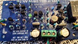
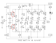
437mV output offset isn't going to be harmful to either the YICDF4 board or to the F4 itself. The F4 is AC coupled between the input JFETs and the output push-pull followers, so the 437mV offset gets blocked by C1,C2 (in red) and does not propagate to the final loudspeaker output.
The only detriment is that your maximum unclipped sine wave amplitude won't be +20V to -20V; instead it will be +19.563V to -19.563V . With an 8 ohm load that's 25 watts with no offset and 23.9 watts with 437mV of offset. I suggest you not worry about it.
_
The only detriment is that your maximum unclipped sine wave amplitude won't be +20V to -20V; instead it will be +19.563V to -19.563V . With an 8 ohm load that's 25 watts with no offset and 23.9 watts with 437mV of offset. I suggest you not worry about it.
_
Attachments
Just in case if @PJN is using Yes It Can Drive An F4 boards but not driving an actual F4, he may wish to study the next piece of gear in the chain and possibly install an AC coupling capacitor after YICDAF4. Two that I can highly recommend are
Mouser P/N 667-ECW-FE2W475J . . . Panasonic, polypropylene film, 4.7 microfarads, 450 volts, 26x12 mm , 22.5 mm lead spacing, luxuriously long lead wires
Mouser P/N 80-PHE426HD7470JR6L2 . . . KEMET, polypropylene film, 4.7 microfarads, 250 volts, 26x15.5mm , 22.5 mm lead spacing, 4 mm long lead wires
Build complete and my impressions. I built my copy as a stand alone preamp using a VDRN psu (great PSU) and a bunch of scavenged parts from old projects. I have a F4 and have driven it with a high gain Aikido tube pre, and a BA3 FE. The Aikido is a nice combo, but is ever so slightly veiled compared to the BA3 FE. Besides that the overall presentation is pretty equivalent. I kept going back and forth between the two. But in my opinion the preamp design gifted by Mark is a step up from both. The dynamics, clarity, and base resolution are better and it not a subtle difference. A really great match for the F4. Really brought mine alive. Congratulations and thanks to Mark for a great design. And thanks to Dan (birdbox) for the kits and all of his help.
Oh hey, @PJN , did you install the output caps recommended in post #113 above? If not, I strongly recommend you do. You've got a standalone preamp that someone else, or forgetful you, might someday connect to another piece of gear. And if that gear happens not to be AC coupled like F4 is AC coupled, there could be a disaster. Honestly I didn't imagine that anyone would put YICDF4 boards anywhere else except inside an F4 chassis and I didn't plan for that. Literally you "thought outside the box" enormously better than I did; protect yourself please.
Hi Mark,
I did install the caps that you recommended to test and burn in the preamp on a garage system, but removed them when I hooked it up to my F4. The fine qualities of this preamp were immediately noticable on my garage system with the output caps.
I did install the caps that you recommended to test and burn in the preamp on a garage system, but removed them when I hooked it up to my F4. The fine qualities of this preamp were immediately noticable on my garage system with the output caps.
For paranoid safety, use one of those label printers to make sticky labels which say "DO NOT CONNECT TO ANYTHING BUT AN F4" and attach the stickers to the rear panel and bottom panel of your 2 x YICDF4 preamp. Otherwise well-meaning people may connect it to something else and then you'll WISH you had installed the output caps.
- Home
- Amplifiers
- Pass Labs
- Yes It Can Drive An F4 -- an example circuit using tightly matched bipolar transistors