
Outstanding work @birdbox !! Besides spectacular craftsmanship, you win the Speedy Gonzales award: 39 days from (Gerber files unveiled) to (working amplifier with swing and slam). Wowzers.
Good on ya!
He was also the first one to finish building his zenductor 2s at Burning Amp…. Show off!
Kidding aside congrats on the beautiful build!
Hello everyone.
I have the situation that I need more voltage gain in front of my F4.
Balanced system, WLS 2018 and F4 monoblocks.
Should I increase the gain of the WLS 2018 or build YICDAF4?
My DAC has an output voltage of 0.5V AC for a 0dB signal - so I measure 0.5V AC to ground on the +/- pin of the XLR socket when I play a signal with 1kHz 0dB.
WLS 2018 has a gain of about 4x.
My speakers have an efficiency of 91dB. Unfortunately, I don't understand the math required to calculate the gain structure of my system.
Thank you very much for your help!
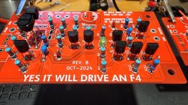
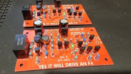
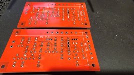
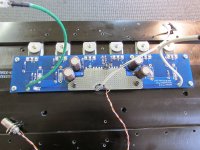
Built up a second set of "Yes It Will Dive An F4" boards for F4 number two. Waiting for F4 parts from Mouser now to complete the main boards.
I populated all the parts starting with the middle of the board first to maximize access with the soldering iron. I was careful to install in an order that maximized soldering tip access, which I highly recommend.
Of course, I left the big parts off until the very end. For the matched BJTs (got 0.1mV matches!), I zip tied them together before installing on the board. I was able to clean the board with the zip tie in place, so I didn't have to cut it off and reinstall a new zip tie after cleaning. Prior to installing the Electrolytic caps, inductors, and film caps, I cleaned the entire board top and bottom thoroughly (many times) with 91% Iso-P (I didn't have 99% on hand) and an old tooth brush, then finished the last big boy parts, and one final bottom cleaning after that.
Attachments
-
 20241225_205616.jpg497.3 KB · Views: 91
 -
 20241226_001757.jpg587.8 KB · Views: 89
 -
 20241225_211944.jpg502.4 KB · Views: 95
 -
 20241225_205707.jpg426.1 KB · Views: 87
 -
 20241225_205701.jpg494.5 KB · Views: 88
 -
 20241225_205631.jpg512.3 KB · Views: 93
 -
 20241225_205627.jpg480.4 KB · Views: 89
 -
 20241225_205622.jpg520.1 KB · Views: 92
Looks great birdbox! Don't forget just a small dab of thermal grease between those two guys with the zipties. Maybe you have some there already, but usually you can see a little squish out when it's there. You can see a hint of it on my old F4 boards here. Also showing a piggyback idea I didn't quite complete that was going to hold lhquam's "Curly-F4", a folded cascode gain stage similar to the LSK pre presented at BAF 2013.
Attachments
Beautiful job, @birdbox !! Have a high-five for stuffing the diodes with abutted cathode & flywire anode. And a second high-five for managing to get all of the TO-92's perfectly vertical and exactly the same height, that's not easy. Btw I like to do one final IPA flood/rinse, followed immediately by a pistol grip hair dryer on maximum blowing speed. It prevents slow evaporation that can leave a powdery haze behind.
Hi Dirk,
I don't know if I am the right man, but I shall be delighted to help you if I can.
I would though need a bit more information.
In a perfect world we would need to know:
If all that sounds too complicated, there is a much easier way. Alternatively if you have another source (idealy something with the quite common 2Vrms output or at least an output you do know exactely as the one you measured) and you know if that one is OK for you... or even too loud (volume position in that case), we could make things much much easier!
My DAC has an output voltage of 0.5V AC for a 0dB signal - so I measure 0.5V AC to ground on the +/- pin of the XLR socket when I play a signal with 1kHz 0dB.
=> OK. I am not used to balanced connection, but correct me if my understanding is wrong. You measure 0.5Vrms between + and - ?
Or is it you measure 0.5V "peak to peak" between the + and -? (eg. "top of the sinus curve" vs rms of the sinus curve).
It makes a small difference so it would be best to know as otherwise we may add more and more "safety margin"...
Note that in all cases this is a very lowish output voltage for a DAC, unusual...
WLS 2018 has a gain of about 4x
=> Noted.
I haven't built the F4, but my understanding is it has no voltage gain. Looking at the schematic it might even have some losses. I am assuming a voltage gain of say "roughly" 0.9 is easonable for an F4 from input to output, do you confirm?
Should I increase the gain of the WLS 2018 or build YICDAF4?
=> You will decide based on what voltage gain you REALLY need!
Thank you very much for your help!
=> Let's see if we get anywhere first LOL
bb
Claude
I don't know if I am the right man, but I shall be delighted to help you if I can.
I would though need a bit more information.
In a perfect world we would need to know:
- what max dB you want to reach at your ears
- what real soundpressure your LS produce (preferably a test where we can look at 1kHz and XX dB/YV/m, Y being usualy 2 or 2.83 etc.)
- your listening distance, room
- we need some margin as all records are far from being optimised re recording level (good old records aren't and that's often better for us)
If all that sounds too complicated, there is a much easier way. Alternatively if you have another source (idealy something with the quite common 2Vrms output or at least an output you do know exactely as the one you measured) and you know if that one is OK for you... or even too loud (volume position in that case), we could make things much much easier!
My DAC has an output voltage of 0.5V AC for a 0dB signal - so I measure 0.5V AC to ground on the +/- pin of the XLR socket when I play a signal with 1kHz 0dB.
=> OK. I am not used to balanced connection, but correct me if my understanding is wrong. You measure 0.5Vrms between + and - ?
Or is it you measure 0.5V "peak to peak" between the + and -? (eg. "top of the sinus curve" vs rms of the sinus curve).
It makes a small difference so it would be best to know as otherwise we may add more and more "safety margin"...
Note that in all cases this is a very lowish output voltage for a DAC, unusual...
WLS 2018 has a gain of about 4x
=> Noted.
I haven't built the F4, but my understanding is it has no voltage gain. Looking at the schematic it might even have some losses. I am assuming a voltage gain of say "roughly" 0.9 is easonable for an F4 from input to output, do you confirm?
Should I increase the gain of the WLS 2018 or build YICDAF4?
=> You will decide based on what voltage gain you REALLY need!
Thank you very much for your help!
=> Let's see if we get anywhere first LOL
bb
Claude
Thank you very much for your answers.
As I am currently on vacation, I cannot carry out any further measurements to determine the gain structure of my system more precisely.
As soon as I am back from vacation, I will take care of it.
On the other hand, I will build YIWDAF4 and see how I like it.
This also gives me additional flexibility in choosing the preamplifier.
The Iron Turtle from ZenMod, for example, is a real temptation.
Excellent catch! That had totally slipped my mind last night around midnight. I ordered some MX-4 thermal grease from the big bookstore and will have to cut the ziptie to apply, then re-ziptie. Keen eyes good sir! Thank you.Don't forget just a small dab of thermal grease
I did hold the boards in front of a little electric blowing heater for that purpose after final rinse, however, I'm going to use your method and take advantage of my heat gun on "high flow/low heat" going forward as I like your idea of direct rapid convective heating to maximize evaporation. I've ordered some 99% IsoP from the big bookstore so when it arrives Saturday (hopefully same day the Mouser order for F4 parts shows up), I'll do a few more rinsing cycles of the PCBs. Thanks again for the wonderful design and expert advice!one final IPA flood/rinse, followed immediately by a pistol grip hair dryer on maximum blowing speed
@birdbox,
Here is the method I use. Works well for me. Also for others if they would like to know:
Best,
Anand.
Here is the method I use. Works well for me. Also for others if they would like to know:
njepitt,
Are you using at least some liquid flux prior to soldering the components? It would make life easier and you won't have to use an excess of solder. This is particularly important with SMD components. In fact, with SMD, I use a liquid solder pen. I also don't solder SMD and some thru hole components without a Yoctosun headlamp or equivalent.
Whether thru hole or SMD, some of these PCB's are quite thick and need a soldering iron and soldering tip with good thermal capacity, but flux certainly helps tremendously. One can wait a very long time...
Best,
Anand.
@poseidonsvoice
Thanks for sharing your method!
I use liquid flux for SMD, but not for thru hole. I do think the idea of a heat lamp is interesting, but I've never had any issues soldering thru hole parts without flux. I guess I should have mentioned in my earlier post that I soldered the YIWDAF4 boards from top first, then the bottom wherever needed so parts don't fall out when I flip the board upside-down. That's why I was careful in the order I installed components for solder tip access.
I've been using a new solder while on holiday in Minnesota with great success (LOCTITE C 400 SN63/47 3C 0.61mm S - "Crystal 400"). Just takes a little extra effort and 99% IsoP to get the residual core flux off the boards. My typical solder I use at home is Fire-Metall and Cardas Quad Eutectic.
@birdbox
That was an old post of mine…
Upon reflection, I’ve been using liquid flux as well for SMD not the pen version but the dropper version. Either is probably fine as long as there is sufficient flux. And lately with Fire-Metall and Cardas Quad Eutectic on thru hole parts I’ve been using them without any additional flux. Can be a messier cleanup afterwards.
Thanks again for the excellent piece of kit you sent me. I will likely make them for balanced mono bridged monoblock F4’s. Dropping the gain a smidge (about 6dB) on each of the YIWDAF4 boards will be a fun exercise I will work on and document here. I believe each board is set for 20X or 26dB gain. I’m going to try 10X or 20dB for each board and verify stability. But I should be able to reverse it back to the original if
Best,
Anand.
Last edited:
Anand, I should have clicked on your link in post #72 as I only read the info showing in the post above, which wasn't the entire link. I clearly responded based on the comments about soldering with flux and not how you clean the boards. Thanks for the information! I'll try it out and see how it works. I'll have to buy some distilled water first though.
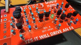
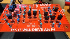
Cleaned up the board further using 99% IsoP and the heat gun technique. Also added Arctic MX-4 thermal grease between the Q5 & Q9 matched BC546C BJTs.
Thanks to @Mark Johnson , @william2001 , and @poseidonsvoice for the guidance!
Now I'm just waiting for the Mouser order for the F4 PCB parts. UPS 2nd day air is actually 4 day air (2 day air is a big lie). I recommend FedEx or USPS as UPS is no bueno in my experience.

Thanks to @Mark Johnson , @william2001 , and @poseidonsvoice for the guidance!
Now I'm just waiting for the Mouser order for the F4 PCB parts. UPS 2nd day air is actually 4 day air (2 day air is a big lie). I recommend FedEx or USPS as UPS is no bueno in my experience.
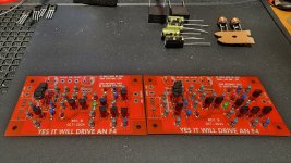
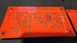
I got my "Yes It Will Drive An F4" boards all populated and ready to install this weekend in my dual mono F4.
I'm posting pics before and after cleaning (99% IsoP with a cheap sonic toothbrush) to see if anyone notices an error before they go into the amp.
I was able to get really good matching of the BC546C pairs using a meticulous matching method (sub 0.1mV!!!) I will share as a "how to" video in the future. I will zip tie the matched pairs together before install.
I'll use DBT for first power up and then variac as a backup mitigation.
Thanks in advance for the keen eyes of the hive diyaudio mind.
View attachment 1393521View attachment 1393522
View attachment 1393525
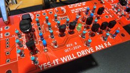
Red and White... Right and Left. Yikes... when asked I just requested both blue.
NOTE: the picture above with the boards built into the F4 has them backwards? The red board is on the left channel and the white on the right!
OK, so I need a order a power supply ( most likely a brick ) and some parts ( rca jacks, barrel connector for the PS.. LEDs?
I found a Japanese cookie metal box that will fit this nicely.
Hmmm.. short edit time..
I guess I missed something.. what's the point of zip tying those two transistors back to back? Heat matching?
Is the zip tie material special or will just plain "black" will do?
I guess I missed something.. what's the point of zip tying those two transistors back to back? Heat matching?
Is the zip tie material special or will just plain "black" will do?
These days I had to up the power dissipation on some sits and it wasn’t working anymore without thermal paste so I added some (exactly like yours) between the sit and its insulator, left it without between insulator and heatsink.Arctic MX-4
At 75w of dissipation on the sit the capsule was getting at 77C without the grease and now it stays at 63C.
So I can say the MX-4 is quite good.
- Home
- Amplifiers
- Pass Labs
- Yes It Can Drive An F4 -- an example circuit using tightly matched bipolar transistors