Small Heatsinks
Hello Syn08
What is the Small heatsink you use H204, do you have specs of it
Regards
AR
Hello Syn08
What is the Small heatsink you use H204, do you have specs of it
Regards
AR
Re: Small Heatsinks
Aavid Thermalloy, an older version of this. Got them from a surplus store. They have around 20 C/W.
PHEONIX said:What is the Small heatsink you use H204, do you have specs of it
Aavid Thermalloy, an older version of this. Got them from a surplus store. They have around 20 C/W.
MLED81
Hello Syn08
D102 is a MLED81 which is an infrared led is a red led a suitable replacement for this part or is there more too it.
Can I ask what the measured THD of this amp is at 100W @20Khz into 8R, the level of the individulal spectrum of components would be nice too.
Regards
AR
Hello Syn08
D102 is a MLED81 which is an infrared led is a red led a suitable replacement for this part or is there more too it.
Can I ask what the measured THD of this amp is at 100W @20Khz into 8R, the level of the individulal spectrum of components would be nice too.
Regards
AR
Re: MLED81
I've asked for these diodes. The PCB-photo shows that they are green.
Here is the syn08's answer
PHEONIX said:D102 is a MLED81 which is an infrared led is a red led a suitable replacement for this part or is there more too it.
I've asked for these diodes. The PCB-photo shows that they are green.
Here is the syn08's answer
Re: MLED81
Don't know for sure yet, but it's certainly under 1ppm (0.0001%). Currently I'm feeding the amp from two switching mode lab supplies (DLM 60-10). Their switching frequency is around 60KHz, so I can't get accurate spectra due to the switching artifacts. Anyway, the second harmonic is clearly dominant, around 8dB over the third, and spectral components are monotonically decreasing with the order.
You got the answer about D102/D117. D103 is a whatever red LED, it's role is only to (on board) signal the error (overcurrent latching) condition.
PHEONIX said:Can I ask what the measured THD of this amp is at 100W @20Khz into 8R, the level of the individulal spectrum of components would be nice too.
Don't know for sure yet, but it's certainly under 1ppm (0.0001%). Currently I'm feeding the amp from two switching mode lab supplies (DLM 60-10). Their switching frequency is around 60KHz, so I can't get accurate spectra due to the switching artifacts. Anyway, the second harmonic is clearly dominant, around 8dB over the third, and spectral components are monotonically decreasing with the order.
You got the answer about D102/D117. D103 is a whatever red LED, it's role is only to (on board) signal the error (overcurrent latching) condition.
Slew rate
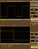
I was finally able, using my digital scope, to capture the (small signal) slew rate of the YAP 2.1 amp. The amp is non slewing, so it is now obvious that the input RF filter and the output coil is defining the rise/fall times.
I removed the imput cap, the output coil and zobel network and applied a 1MHz signal from a PM5193 50MHz pulse generator, with rise time around 1nS. The 50 ohm impedance output level was about 40mVpp, set to give a 500mVpp output (1MHz is slightly beyond the -3dB point, so the gain was lower than 28dB). A 50ohm resistor was placed at the YAP input to match the cable impedance.
The results are shown in the picture below. Rise and fall times are symmetrical and about 10nS, yelding a small signal slew rate (10% - 90%) of about 400V/uS. Doubling the signal input (not shown) approximately doubles the rise/fall times.
Attachments
J102 protection
Hello Syn08
Does the connector J102 connect to a relay which disconnects the amplifier output from the speaker in fault mode. What relay do you use.
By the way how much power do you does this amp develop into 8R.
Regards
AR
Hello Syn08
Does the connector J102 connect to a relay which disconnects the amplifier output from the speaker in fault mode. What relay do you use.
By the way how much power do you does this amp develop into 8R.
Regards
AR
Re: J102 protection
J102 goes to an "analog computer" that monitors all the fault conditions (overload (J102) output offset (using TA7317) temperature (including fans control), power supply faults) and manages the power sequencing, etc... It's a pretty complicated beast, the starting point is "Auxilliary circuitry" in the PGP amp (see my web site about), the YAP version is currently still in development.
The output power depends on the power supply; using two 800W toroids and +/-80W rails, the amp delivers continuous 2x300W RMS into 8ohm. This power levels will for sure require fan support at some time, though.
You don't need to do any changes in the schematic for rail voltages down to +/-50V.
PHEONIX said:Does the connector J102 connect to a relay which disconnects the amplifier output from the speaker in fault mode. What relay do you use.
By the way how much power do you does this amp develop into 8R.
J102 goes to an "analog computer" that monitors all the fault conditions (overload (J102) output offset (using TA7317) temperature (including fans control), power supply faults) and manages the power sequencing, etc... It's a pretty complicated beast, the starting point is "Auxilliary circuitry" in the PGP amp (see my web site about), the YAP version is currently still in development.
The output power depends on the power supply; using two 800W toroids and +/-80W rails, the amp delivers continuous 2x300W RMS into 8ohm. This power levels will for sure require fan support at some time, though.
You don't need to do any changes in the schematic for rail voltages down to +/-50V.
PSRR
Hello Syn08
What is the PSRR of whole amp with respect to + and - voltage supplies ( simulation wise)
Regards
AR
Hello Syn08
What is the PSRR of whole amp with respect to + and - voltage supplies ( simulation wise)
Regards
AR
Re: Slew rate
Very Nice!
Best,
Bob
syn08 said:I was finally able, using my digital scope, to capture the (small signal) slew rate of the YAP 2.1 amp. The amp is non slewing, so it is now obvious that the input RF filter and the output coil is defining the rise/fall times.
I removed the imput cap, the output coil and zobel network and applied a 1MHz signal from a PM5193 50MHz pulse generator, with rise time around 1nS. The 50 ohm impedance output level was about 40mVpp, set to give a 500mVpp output (1MHz is slightly beyond the -3dB point, so the gain was lower than 28dB). A 50ohm resistor was placed at the YAP input to match the cable impedance.
The results are shown in the picture below. Rise and fall times are symmetrical and about 10nS, yelding a small signal slew rate (10% - 90%) of about 400V/uS. Doubling the signal input (not shown) approximately doubles the rise/fall times.
Very Nice!
Best,
Bob
Re: PSRR
Anywhere between -70dB and -80dB for both PSRR+ and PSRR- I don't have any idea how much it is in practice (with component mismatches, etc...).
PHEONIX said:What is the PSRR of whole amp with respect to + and - voltage supplies ( simulation wise)
Anywhere between -70dB and -80dB for both PSRR+ and PSRR- I don't have any idea how much it is in practice (with component mismatches, etc...).
Re: Re: PSRR
Hello Syn08
I presume this at DC what is it at 20Khz
Regards
AR
syn08 said:
Anywhere between -70dB and -80dB for both PSRR+ and PSRR- I don't have any idea how much it is in practice (with component mismatches, etc...).
Hello Syn08
I presume this at DC what is it at 20Khz
Regards
AR
Hello syn08
It would be interesting to measure the distortion on your amp to see if it confirms the simulation results.
Does anyone have an Audio Precision that they wouldn't mind lending ?? 😉
regards
Trevor
It would be interesting to measure the distortion on your amp to see if it confirms the simulation results.
Does anyone have an Audio Precision that they wouldn't mind lending ?? 😉
regards
Trevor
Re: Re: Re: PSRR
About the same.
PHEONIX said:
I presume this at DC what is it at 20Khz
About the same.
Trevor White said:It would be interesting to measure the distortion on your amp to see if it confirms the simulation results.
Don't worry, measurements are coming 🙂 For this particular toplology, the simulations (and in particular for distortions) are zilch, unless you have a good device level model for the opamp.
I would like to hear your comparison of measurement results to listening results.
I hope it turns out to be worth all the effort and design skills you have thrown at it.
I'll be patient.
I hope it turns out to be worth all the effort and design skills you have thrown at it.
I'll be patient.
AndrewT said:I would like to hear your comparison of measurement results to listening results.
I hope it turns out to be worth all the effort and design skills you have thrown at it.
I'll be patient.
It's on the todo list. I'm though not expecting any major subjective differences to (e.g.) the PGP amp, except for solving the 4ohm issues.
What I am really curious is to find out if there are any subjective differences between a MOSFET and a bipolar amp, both in the same objective performance range (YAP vs. VSOP).
VSOP amp
Hello Syn08
Ultimately what was the THD performance difference between the VSOP best implementation versus Yap 2.1. You comment about sound difference between the two amps where they made with the same passives electros etc.
Regards
AR
Hello Syn08
Ultimately what was the THD performance difference between the VSOP best implementation versus Yap 2.1. You comment about sound difference between the two amps where they made with the same passives electros etc.
Regards
AR
Is it possible to join you in the listening test ? 🙄syn08 said:It's on the todo list. I'm though not expecting any major subjective differences to (e.g.) the PGP amp, except for solving the 4ohm issues.
- Status
- Not open for further replies.
- Home
- Amplifiers
- Solid State
- YAP power amp revisited, now at v2.1