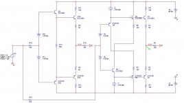
May be it would be interesting. This amp uses Tektronix cascode (about 5-10dB or more better than Hawksford) and the same OPS input stage.
Here is the schematic:
http://www.vegalab.ru/forum/attachment.php?attachmentid=50084&d=1239179731
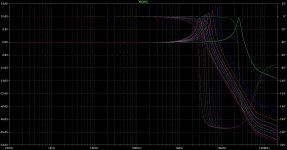
Measured THD 10kHz 25Vp-p 7Ohm with no feedback (top graph):
http://www.vegalab.ru/forum/attachment.php?attachmentid=51265&d=1240574419
Measured THD 1kHz 25Vp-p 7Ohm with no feedback (top graph):
http://www.vegalab.ru/forum/attachment.php?attachmentid=51262&d=1240574364
There are some measurements with no output transistors (Q30-31), but only for 1kHz (about -100dB).
Here is the link to the thread in russian http://www.vegalab.ru/forum/showthread.php?t=21173
Link to the Tektronix cascode patent http://www.google.com/patents?id=C4...rce=gbs_overview_r&cad=0#v=onepage&q=&f=false
Here is the schematic:
http://www.vegalab.ru/forum/attachment.php?attachmentid=50084&d=1239179731
Measured THD 10kHz 25Vp-p 7Ohm with no feedback (top graph):
http://www.vegalab.ru/forum/attachment.php?attachmentid=51265&d=1240574419
Measured THD 1kHz 25Vp-p 7Ohm with no feedback (top graph):
http://www.vegalab.ru/forum/attachment.php?attachmentid=51262&d=1240574364
There are some measurements with no output transistors (Q30-31), but only for 1kHz (about -100dB).
Here is the link to the thread in russian http://www.vegalab.ru/forum/showthread.php?t=21173
Link to the Tektronix cascode patent http://www.google.com/patents?id=C4...rce=gbs_overview_r&cad=0#v=onepage&q=&f=false
Last edited:
Interesting, I'll take a closer look.
On the top of my head, I have some concerns regarding the stability, at least in the configuration described in the patent. This thing seems to be designed having in mind open loop only.
On the top of my head, I have some concerns regarding the stability, at least in the configuration described in the patent. This thing seems to be designed having in mind open loop only.
BTW, I've noticed similarities between the YAP OPS and the Jeff Rowland M9 early amp:
http://www.diyaudio.com/forums/showpost.php?p=1651648&postcount=11
Similar diamond buffer, similar VAS topology, etc...
http://www.diyaudio.com/forums/showpost.php?p=1651648&postcount=11
Similar diamond buffer, similar VAS topology, etc...
I think it should be ok for not very high feedback-loop unity-gain frequency (depends on type of transistors).This thing seems to be designed having in mind open loop only.
Last edited:
Still doesn’t outperform a basic double EF input stage.
Total Harmonic Distortion: 0.084865%
Total Harmonic Distortion: 0.123628%
Ok Glen, it seems like you need a lesson in simulation and how much you may rely on that.
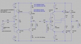
I did something I rarely do, that is I tried to reproduce your results and get some further conclusions. The schematic is attached. Of course, I am using PSpice, which is different (I guess) to your toy but not that much different in the core to Edmond's toy.
Here are my results. Ro stands for R14=R15 in the schematics.
--------------------------------------------------------
Ro=0kohm
FOURIER COMPONENTS OF TRANSIENT RESPONSE V(OUT1)
DC COMPONENT = -1.191226E-02
HARMONIC FREQUENCY FOURIER NORMALIZED PHASE NORMALIZED
NO (HZ) COMPONENT COMPONENT (DEG) PHASE (DEG)
1 2.000E+04 2.992E+01 1.000E+00 -4.193E-04 0.000E+00
2 4.000E+04 6.194E-05 2.070E-06 -9.068E+01 -9.068E+01
3 6.000E+04 1.208E-05 4.039E-07 3.432E+01 3.432E+01
4 8.000E+04 1.015E-06 3.394E-08 6.846E+00 6.848E+00
5 1.000E+05 1.483E-06 4.958E-08 -2.752E+01 -2.752E+01
6 1.200E+05 3.833E-07 1.281E-08 -2.586E+01 -2.586E+01
7 1.400E+05 2.051E-07 6.854E-09 1.618E+02 1.618E+02
8 1.600E+05 1.698E-07 5.677E-09 1.588E+02 1.588E+02
9 1.800E+05 6.586E-07 2.201E-08 -1.044E+02 -1.044E+02
10 2.000E+05 1.157E-06 3.869E-08 -4.597E+01 -4.596E+01
TOTAL HARMONIC DISTORTION = 2.110731E-04 PERCENT
FOURIER COMPONENTS OF TRANSIENT RESPONSE V(OUT2)
DC COMPONENT = -1.105978E-02
HARMONIC FREQUENCY FOURIER NORMALIZED PHASE NORMALIZED
NO (HZ) COMPONENT COMPONENT (DEG) PHASE (DEG)
1 2.000E+04 2.992E+01 1.000E+00 -6.541E-04 0.000E+00
2 4.000E+04 3.385E-05 1.131E-06 -7.451E+01 -7.451E+01
3 6.000E+04 1.641E-05 5.483E-07 5.126E+01 5.126E+01
4 8.000E+04 8.495E-07 2.839E-08 4.070E+01 4.070E+01
5 1.000E+05 1.751E-06 5.853E-08 -3.507E+01 -3.507E+01
6 1.200E+05 1.793E-06 5.993E-08 9.529E+00 9.533E+00
7 1.400E+05 7.772E-07 2.598E-08 1.684E+02 1.684E+02
8 1.600E+05 6.205E-07 2.074E-08 1.024E+02 1.024E+02
9 1.800E+05 2.399E-06 8.019E-08 -1.021E+02 -1.021E+02
10 2.000E+05 2.121E-06 7.090E-08 5.234E+01 5.235E+01
TOTAL HARMONIC DISTORTION = 1.265352E-04 PERCENT
------------------------------------------------------------------------
Ro=10kohm
FOURIER COMPONENTS OF TRANSIENT RESPONSE V(OUT1)
DC COMPONENT = -1.966295E-01
HARMONIC FREQUENCY FOURIER NORMALIZED PHASE NORMALIZED
NO (HZ) COMPONENT COMPONENT (DEG) PHASE (DEG)
1 2.000E+04 2.986E+01 1.000E+00 -4.176E-01 0.000E+00
2 4.000E+04 1.222E-02 4.092E-04 -1.549E+01 -1.465E+01
3 6.000E+04 1.104E-02 3.696E-04 9.260E+01 9.385E+01
4 8.000E+04 6.936E-04 2.323E-05 -1.068E+02 -1.051E+02
5 1.000E+05 3.086E-03 1.033E-04 -7.966E+01 -7.757E+01
6 1.200E+05 1.062E-03 3.557E-05 -2.651E+01 -2.401E+01
7 1.400E+05 1.749E-03 5.856E-05 3.093E+01 3.385E+01
8 1.600E+05 6.839E-04 2.290E-05 -3.136E+01 -2.802E+01
9 1.800E+05 6.944E-04 2.325E-05 1.372E+02 1.409E+02
10 2.000E+05 1.872E-04 6.267E-06 -9.268E+01 -8.851E+01
TOTAL HARMONIC DISTORTION = 5.666040E-02 PERCENT
FOURIER COMPONENTS OF TRANSIENT RESPONSE V(OUT2)
DC COMPONENT = -1.017697E-01
HARMONIC FREQUENCY FOURIER NORMALIZED PHASE NORMALIZED
NO (HZ) COMPONENT COMPONENT (DEG) PHASE (DEG)
1 2.000E+04 2.991E+01 1.000E+00 -9.062E-03 0.000E+00
2 4.000E+04 3.264E-04 1.091E-05 -1.672E+01 -1.670E+01
3 6.000E+04 2.233E-04 7.465E-06 1.079E+02 1.079E+02
4 8.000E+04 2.950E-05 9.862E-07 1.328E+02 1.329E+02
5 1.000E+05 6.809E-05 2.276E-06 -8.264E+01 -8.260E+01
6 1.200E+05 5.338E-05 1.785E-06 -1.225E+02 -1.225E+02
7 1.400E+05 4.325E-05 1.446E-06 9.986E+01 9.992E+01
8 1.600E+05 1.586E-05 5.301E-07 -1.751E+02 -1.750E+02
9 1.800E+05 2.798E-05 9.354E-07 -9.514E+01 -9.506E+01
10 2.000E+05 2.441E-05 8.161E-07 -6.739E+01 -6.730E+01
TOTAL HARMONIC DISTORTION = 1.371169E-03 PERCENT
------------------------------------------------------------------------
Ro=100kohm
FOURIER COMPONENTS OF TRANSIENT RESPONSE V(OUT1)
DC COMPONENT = -1.818206E+00
HARMONIC FREQUENCY FOURIER NORMALIZED PHASE NORMALIZED
NO (HZ) COMPONENT COMPONENT (DEG) PHASE (DEG)
1 2.000E+04 2.930E+01 1.000E+00 -4.147E+00 0.000E+00
2 4.000E+04 1.182E-01 4.036E-03 -1.692E+01 -8.622E+00
3 6.000E+04 9.268E-02 3.163E-03 7.242E+01 8.486E+01
4 8.000E+04 2.879E-02 9.827E-04 1.262E+02 1.428E+02
5 1.000E+05 1.627E-02 5.555E-04 -1.097E+02 -8.892E+01
6 1.200E+05 5.589E-03 1.908E-04 1.772E+02 2.020E+02
7 1.400E+05 8.036E-03 2.743E-04 -1.531E+01 1.372E+01
8 1.600E+05 8.054E-03 2.749E-04 1.336E+02 1.667E+02
9 1.800E+05 4.745E-03 1.620E-04 6.531E+01 1.026E+02
10 2.000E+05 6.193E-03 2.114E-04 1.312E+02 1.726E+02
TOTAL HARMONIC DISTORTION = 5.275554E-01 PERCENT
FOURIER COMPONENTS OF TRANSIENT RESPONSE V(OUT2)
DC COMPONENT = -9.167653E-01
HARMONIC FREQUENCY FOURIER NORMALIZED PHASE NORMALIZED
NO (HZ) COMPONENT COMPONENT (DEG) PHASE (DEG)
1 2.000E+04 2.988E+01 1.000E+00 -8.241E-02 0.000E+00
2 4.000E+04 3.282E-03 1.098E-04 -7.397E+00 -7.232E+00
3 6.000E+04 2.096E-03 7.014E-05 9.124E+01 9.148E+01
4 8.000E+04 6.247E-04 2.090E-05 1.700E+02 1.703E+02
5 1.000E+05 6.166E-04 2.063E-05 -6.723E+01 -6.682E+01
6 1.200E+05 2.488E-04 8.326E-06 -1.404E+01 -1.355E+01
7 1.400E+05 1.232E-04 4.122E-06 3.763E+01 3.820E+01
8 1.600E+05 1.466E-04 4.906E-06 -6.399E+01 -6.333E+01
9 1.800E+05 1.216E-04 4.069E-06 3.674E+01 3.748E+01
10 2.000E+05 1.802E-04 6.032E-06 3.951E+00 4.775E+00
TOTAL HARMONIC DISTORTION = 1.341988E-02 PERCENT
---------------------------------------------------------------------
As you see, my results are completely different to yours. While at Ro=0 both approaches (OUT1 is the double EF, OUT2 is the bootstrap version) are delivering very low THD20 (2.1ppm vs. 1.3ppm), as Ro increases, and as expected, the distortions increase dramatically; at Ro=10kohm it's 57ppm vs. 14ppm while at Ro=100kohm it's 0.53% vs. 0.013%.
This is an expected result, and you would of course notice that the bootstraped version always outperforms the double EF, by a significant margin. Is this true in the real life? I don't have the foggiest idea...
Conclusions?
- I don't know if my results are correct, and I have no intention to further pursue this matter, experimentally of simulation wise.
- What I know is that the THD20 simulation in PSpice is correct and that the 2SA/2SC models are the ones from Fairchild, which seem to be pretty accurate.
- This example confirms and re-confirms that simulation results, at least the way you are using them, are not worth the electrons required to post a message on this forum.
- You would of course notice that I stubbornly refuse to present simulation results, although I simulate my stuff carefully and throughly. Why? Because I refuse to let out something that usually can't be objectively checked and crosschecked by others, see the above example. That's simply because an out-of-the-box comparison of any fairly complex stuff (in particular distortions and nonlinear transient stuff) is usually flat wrong, and those relying on such comparisons are simmy-fools.
- Now, comparing simulations is nowhere easier than comparing and reproducing measurements; simulators have to be tested, compared and calibrated, models have to be crosschecked, common benchmarks have to be defined, etc... I did this in the past as a professional, and trust me, it's hell on earth, no less than a full time job. I would kindly remind you that I used to work with Cadence while they took over the Orcad products. I know pretty well the PSpice code, and if there's anybody around knowing "a little" about Spice and in particular PSpice, that would be yours truly.
These are the reasons why I usually strongly dislike posts like yours. You gave no resoning, no analysis, no attempt to understand the problem(s). Jump in with something like "your input stage is worse because the nonlinear capacitances are exposed to twice the voltage swing, hence more distortions in the large signal response" and we can talk about; but posting a half baked schematic, with little to no connection to the real world, and a bunch of number straight out of the number cruncher, without any crosschecking or analysis, that's something that qualifies simply as.... you guessed... :bs: You successfully delivered a "mine is longer" approach example, that's all.
Attachments
Last edited:
Ok Glen, it seems like you need a lesson in simulation and how much you may rely on that.
These are the reasons why I usually strongly dislike posts like yours. You gave no resoning, no analysis, no attempt to understand the problem(s). Jump in with something like "your input stage is worse because the nonlinear capacitances are exposed to twice the voltage swing, hence more distortions in the large signal response" and we can talk about; but posting a half baked schematic, with little to no connection to the real world, and a bunch of number straight out of the number cruncher, without any crosschecking or analysis, that's something that qualifies simply as.... you guessed... :bs: You successfully delivered a "mine is longer" approach example, that's all.
Thanks, nice rant.
Now here I can confidently claim that any perceived “mine is longer” approach is mostly a case of projection. I really wasn’t expecting something so benign (which has clearly been taken as some kind of criticism, that it wasn't) to devolve into such a contentious spat.
As I’ve already plainly conceded to Andy, the issue of the non-linear input capacitance is perfectly valid and the bootstrapped version of the input stage clearly addresses this issue; however in a complete amplifier simulation I have not found it to have an impact on non-linearity that I would have expected.
In fact I recall discussing (arguing?) over this with Edmond some time ago (NFB thread?) when I presented a “Hawksford cascode” style of input stage as an alternative to the simple (non-bootstrapped) diamond buffer.
He assured me that in a complete amplifier simulation my “Hawksford cascode” input stage (which bootstraps Cbc) has no real linearity benefit over the conventional diamond buffer. I made the comparison and found this to be true. I then further simplified the input stage; doing away with the extra complication of the biasing CCS’s and turning it into a basic double emitter follower, which performed the same (without surprise), lineariy wise.
As for my schematic being “half baked”, I posted it, along with the simulation results in full, for anyone who so wishes to copy and run and judge the merits and limitations for themselves.
And seriously, this beauty of yours:
“I don't know if my results are correct, and I have no intention to further pursue this matter, experimentally of simulation wise………..is usually flat wrong, and those relying on such comparisons are simmy-fools.”
besides pretty much negating your whole post, is pretty much summed up by this:
“You gave no resoning, no analysis, no attempt to understand the problem(s).”
Isn't it?
Personally, I think that simplified voltage-drive simulation/comparison is quite revealing by itself, as there is more than one distortion mechanism (Hawksfords “slope distortion”) that one could expect to have significant impact here also, but which in reality may not.
But that's another kettle of fish, probably too incendiary in this surreal zoo.
Last edited:
Thanks, nice rant.
You are welcomed, anyway, you still don't get it.
Two simulators, running on the same schematic, using the same models, delivering three orders of magnitude different results.
Double EF: 848ppm vs. 2.1ppm
Bootstrap: 1236ppm vs. 1.1ppm
I couldn't care less what/where is the problem (although I most likely could figure it out), I have better things to do than splicing and dicing the number crunchers, models, parameters, etc... Point is, isolated simulations are not worth a dime and should not be brought alone as arguments in any discussion that pretends to be intelligent.
I've just run my sims again and have had a look at your schematic, and I can see one glaring issue.
However, I’d now like permission to reciprocate your ennui on this topic. Instead I’ve got some new Miles Davis, Cassandra Wilson and Anita Baker CD’s and a pair of Taslima Nasrin novels that I'd prefer to absorb.
Bye bye!
Last edited:
I was hoping not to have to say this, but I'm going to get up on the soapbox anyway.
There's a small group of posters here who I consider the "core", which includes syn08, Glen, Edmond, Bob, and a number of others who I'm sure I've neglected to mention. If this group can't get along (to paraphrase Rodney King), then we will all be Lum-botomized by the lowest common denominator 🙂.
Carry on 😀.
Looks like nobody's is longer🙂.
I simmed these buffers in LTSpice and got practically the same figures as syn08 in PSpice.
What is confusing me is the peaking and sharp phase shift when you run AC analysis of bootstrapped buffer from high impedance source. When bootstrapping transistors are removed everything goes fine, but distortion perfomance becomes definitely worse.
Driving bootstrapped buffer from high impedance VAS looks somewhat problematic.
Regards,
Alex
Attachments
Usually Ccomp capacitor makes the VAS output impedance at high frequencies really low.What is confusing me is the peaking and sharp phase shift when you run AC analysis of bootstrapped buffer from high impedance source. ... Driving bootstrapped buffer from high impedance VAS looks somewhat problematic. ...
Last edited:
I simmed these buffers in LTSpice and got practically the same figures as syn08 in PSpice.
That's encouraging. Looks like Glen was looking at the distortion of the collector current of a single device, while syn08 was looking at the output voltage. Due to the complementary design, I'd expect some cancellation of even-order components in the output voltage that wouldn't happen looking at collector current of one device. Also, I'm not sure the collector current AC component in the actual circuit would be as large as the 1.5 mA peak shown in Glen's analysis, since the CFB in the actual circuit is trying to keep that low. Once the subcircuit is taken out of the rest of the design and placed in isolation, it becomes difficult to reproduce what's going on in the larger circuit at the subcircuit level.
Driving bootstrapped buffer from high impedance VAS looks somewhat problematic.
I'd expect the output impedance of the VAS to not be too large, due to the local Miller feedback around the VAS.
Edit: Oops, I see Nickolay beat me to it while I was posting.
Enhanced cascode
According to Dimitri Danyuk's findings even a 12dB reduction (of high-order distortion products) may be possible. See his paper: "On the Optimization of Enhanced Cascode", presented at the 125th AES convention, 2008 October.
Cheers,
Edmond.
May be it would be interesting. This amp uses Tektronix cascode (about 5-10dB or more better than Hawksford) and the same OPS input stage.
Here is the schematic:
http://www.vegalab.ru/forum/attachment.php?attachmentid=50084&d=1239179731
[snip]
According to Dimitri Danyuk's findings even a 12dB reduction (of high-order distortion products) may be possible. See his paper: "On the Optimization of Enhanced Cascode", presented at the 125th AES convention, 2008 October.
Cheers,
Edmond.
diamond IPS
Hi Allexx, Andy & Nickolay,
I also observed such issues when the value of R15 is too high, that is, higher than say 220 Ohms. In real life however, this impedance is (in most cases) determined by a Miller compensated VAS, which has at HF indeed quite a low output impedance, in the order of 25 to 100 Ohms. So I don't expect serious troubles with that diamond IPS under these conditions.
Cheers,
Edmond.
That's encouraging. Looks like Glen was looking at the distortion of the collector current of a single device, while syn08 was looking at the output voltage. Due to the complementary design, I'd expect some cancellation of even-order components in the output voltage that wouldn't happen looking at collector current of one device. Also, I'm not sure the collector current AC component in the actual circuit would be as large as the 1.5 mA peak shown in Glen's analysis, since the CFB in the actual circuit is trying to keep that low. Once the subcircuit is taken out of the rest of the design and placed in isolation, it becomes difficult to reproduce what's going on in the larger circuit at the subcircuit level.
Hi Andy
I was looking at the collector current instead as this relates to how the input stage/buffer actually operates in a CFB amp.
The 1.5mA peak test current is high, but the distortion ratio between the two circuits is pretty much constant as this is lowered anyway - even at a couple of hundred uA or so (the double EF still wins
 ).
).What is interesting though, is that at low-level signal currents, the overall linearity of both input stages is surprisingly poor; keeping the voltage input at a fixed amplitude, the linearity gets progressively worse as the current swing is reduced (by increasing the value of the load resistor).
This is obviously because the collector-base current flowing through Ccb is an increasing proportion of the total collector current as the signal current swing is reduced. I hope I've worded that in a comprehensible way

Attached is my *.asc file - have a play.
Attachments
Last edited:
Measured THD 10kHz 25Vp-p 7Ohm with no feedback (top graph):
http://www.vegalab.ru/forum/attachment.php?attachmentid=51265&d=1240574419
My understanding of russian are nil, so I can't really follow up on this, but I find those measurements (if they are, as you said, open loop) very hard to believe. -90dB and -87dB 2nd and 3rd harmonic (at 10KHz) with everything else under -120dB is a stunning performance. Could you confirm these numbers?
Has anybody published anything about building this amp? I would also be curious about the construction details.
I've checked the Tek cascode performance in the YAP context and while it indeed raises the OL gain with about 15dB (at LF), I was unable for the moment to get any significant improvement in the overall performance, at least without degrading the phase margin. Not really surprising, the first YAP used a Hawksford cascode in the OPS, and that didn't improve the overall performance either, that's why in YAP 2.1 I gave up completely the cascoded VAS.
I'll keep looking into this toplogy, though.
Yes, that is correct. However the OPS was in class A. It seems that the main source of distortion is OPS, so I guess with no load it could be even better.My understanding of russian are nil, so I can't really follow up on this, but I find those measurements (if they are, as you said, open loop) very hard to believe. -90dB and -87dB 2nd and 3rd harmonic (at 10KHz) with everything else under -120dB is a stunning performance. Could you confirm these numbers?
It's a prototype. The author is Vladimir Mashkov (aka shkal at vegalab.ru forum), and what has been published is in this thread http://www.vegalab.ru/forum/showthread.php?t=21173.Has anybody published anything about building this amp? I would also be curious about the construction details.
Here you can see some photos: http://www.vegalab.ru/forum/showpost.php?p=660757&postcount=46
It seems that such VAS-es are useless for the high feedback loop gain amps, cause the open loop distortions are high anyway. (Though of course the open_loop_distortion/open_loop_gain ratio is very low.)I've checked the Tek cascode performance in the YAP context and while it indeed raises the OL gain with about 15dB (at LF), I was unable for the moment to get any significant improvement in the overall performance, at least without degrading the phase margin. Not really surprising, the first YAP used a Hawksford cascode in the OPS, and that didn't improve the overall performance either, that's why in YAP 2.1 I gave up completely the cascoded VAS.
I'll keep looking into this toplogy, though.
PS.This one could be interesting too http://www.google.com/patents?id=9v...rce=gbs_overview_r&cad=0#v=onepage&q=&f=false Thanks to Sergey Ageev for the links.
Last edited:
Yes, that is correct. However the OPS was in class A.
Ah, ok.
- Status
- Not open for further replies.
- Home
- Amplifiers
- Solid State
- YAP power amp revisited, now at v2.1