Nickolay Shvydky said:Is it possible to join you in the listening test ? 🙄
Haven't made any final plans yet, but of course you may if you are willing to come over here. Rochester NY is across the the lake.
Probably sometimes in Nov or Dec, I'll keep you updated.
Re: VSOP amp
In terms of THD20, YAP 2.1 is one order of magnitude better than the VSOP amp, but in the ppm range these are numbers only. If there is any difference it's not because the THD20.
Both amps are build from stock parts, nothing really special. There are no lytics in the signal path (I don't consider decouplings as such).
PHEONIX said:Ultimately what was the THD performance difference between the VSOP best implementation versus Yap 2.1. You comment about sound difference between the two amps where they made with the same passives electros etc.
In terms of THD20, YAP 2.1 is one order of magnitude better than the VSOP amp, but in the ppm range these are numbers only. If there is any difference it's not because the THD20.
Both amps are build from stock parts, nothing really special. There are no lytics in the signal path (I don't consider decouplings as such).
Caps
Hello Syn08
I am not talking about signal coupling caps, are the amps you compared using for example the sample power supply caps.
Regards
Arthur
Hello Syn08
I am not talking about signal coupling caps, are the amps you compared using for example the sample power supply caps.
Regards
Arthur
Re: Caps
This can be arranged (to use the same power supply, that is).
PHEONIX said:are the amps you compared using for example the sample power supply caps.
This can be arranged (to use the same power supply, that is).
Thank you! I'll be waiting.syn08 said:
Haven't made any final plans yet, but of course you may if you are willing to come over here. Rochester NY is across the the lake.
Probably sometimes in Nov or Dec, I'll keep you updated.
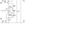
Re: Q114 YAP2.1 output stage
Look at first post (below second image):
"Q114 is shorted for 2SK1530/2SJ201 only"
PHEONIX said:I noticed that Q114 on the schematic you posted (YAP 2.1 output) is effectively shorted out e-b-c are all connected to one another on the 2SA1381 is this correct.
Look at first post (below second image):
"Q114 is shorted for 2SK1530/2SJ201 only"
Hello syn08,
I need some help. I've tried a few simulations and THD levels are close to your measurements (less than 1ppm to 9ppm, depending on power and freq.), but I can't achieve SR 400V/us - only about 80V/us (with input cap, output coil and Zobel network removed; protection is disconnected).
By my calculations, to achieve such SR 400V/us, peak VAS current should be at least 80mA. I assume that Ivas(peak) should be = SR*(C203+C206) + Ivas(bias) = 4E8*2E-10 + 0.013 = 93mA. Can this circuit deliver such current or maybe my assumption is wrong?
In your previous YAP-FE you use TMC and these capacitors are 4 times smaller (27pF in series with 150pF and 1k to out) and SR is 270V/us.
Also I get slight oscillations ~60MHz but they are missing in your measurements. These oscillations appear with Vpulse only, regardless of the level, but they fade out for less than 1us. With R130 and R145 set to 300ohms they fade out for less than 100ns, but Vcb(Q110,Q116) goes less than 1V.
Maybe there are limitations and differences with spice models and analysis or maybe there are errors in my schematic although it is recaptured very carefully and THD levels are fine.
Just I want to be sure that all is fine and to have basis for comparison when I change 2SA1381/2SC3503 to 2SA1360/2SC3423 and power devices with IRFP spice models.
Sorry if my questions are stupid. I don't want to waste your time. Just now I have access to professional Orcad and try to learn and make something useful.
Attachments
Re: Re: Q114 YAP2.1 output stage
Thanks KL
Just one question which version of Cadence are you using, and are the THD simulations consistent, I alway found they varied at very low THD sims on this package. Do you have this problem.
AR
kl said:
Thanks KL
Just one question which version of Cadence are you using, and are the THD simulations consistent, I alway found they varied at very low THD sims on this package. Do you have this problem.
AR
Hello PHEONIX
Orcad version is 16, but I can't say something more about THD simulations. Obviously they are very close to real measurements, but maybe this depends of sipce models. There are different models for same part and results are different.
I found in YAP that THD at 1kHz is more than 20kHz at about 1W. I think this is not real.
Sorry, I am not spice-sim-guru.
kl said:Hello syn08,
I need some help. I've tried a few simulations and THD levels are close to your measurements (less than 1ppm to 9ppm, depending on power and freq.), but I can't achieve SR 400V/us - only about 80V/us (with input cap, output coil and Zobel network removed; protection is disconnected).
By my calculations, to achieve such SR 400V/us, peak VAS current should be at least 80mA. I assume that Ivas(peak) should be = SR*(C203+C206) + Ivas(bias) = 4E8*2E-10 + 0.013 = 93mA. Can this circuit deliver such current or maybe my assumption is wrong?
In your previous YAP-FE you use TMC and these capacitors are 4 times smaller (27pF in series with 150pF and 1k to out) and SR is 270V/us.
Also I get slight oscillations ~60MHz but they are missing in your measurements. These oscillations appear with Vpulse only, regardless of the level, but they fade out for less than 1us. With R130 and R145 set to 300ohms they fade out for less than 100ns, but Vcb(Q110,Q116) goes less than 1V.
Maybe there are limitations and differences with spice models and analysis or maybe there are errors in my schematic although it is recaptured very carefully and THD levels are fine.
Just I want to be sure that all is fine and to have basis for comparison when I change 2SA1381/2SC3503 to 2SA1360/2SC3423 and power devices with IRFP spice models.
Sorry if my questions are stupid. I don't want to waste your time. Just now I have access to professional Orcad and try to learn and make something useful.
Hi,
YAP can't be accurately and reliably simulated, there are no accurate opamp models to allow that.
400V/us, that's under small signal conditions, so the CC source loading a cap Ic/C model doesn't apply, but rather gm*Ub'e/C~40*Ic/C. Large signal SR is measured around 150V/uS (with C203 C206 down to 68pF, that's what I'm running right now with).
The previous YAP was not using TMC in the input stage, it only looks like TMC. The resistor was only to broaden the phase shift peak around the UG frequency.
There are no 60MHz parasitic oscillations in practice, don't know why you got them in simulation, and anyway, a Vce around 1V is perfectly fine.
There are no stupid questions, only stupid answers.
Revisited YAP v2.1
- Improved OPS input stage (following an idea by Andy).
Still doesn’t outperform a basic double EF input stage.

Fourier components of I(doubleef)
DC component:0.0110311
Harmonic Frequency Fourier Normalized Phase Normalized
Number [Hz] Component Component [degree] Phase [deg]
1 2.000e+04 1.506e-03 1.000e+00 -0.23° 0.00°
2 4.000e+04 1.239e-06 8.227e-04 179.94° 180.17°
3 6.000e+04 2.792e-07 1.855e-04 95.78° 96.01°
4 8.000e+04 1.352e-07 8.979e-05 1.44° 1.67°
5 1.000e+05 3.856e-08 2.561e-05 -89.40° -89.18°
6 1.200e+05 2.212e-08 1.469e-05 -179.42° -179.19°
7 1.400e+05 6.680e-09 4.437e-06 90.37° 90.60°
8 1.600e+05 4.124e-09 2.739e-06 0.67° 0.89°
9 1.800e+05 1.259e-09 8.363e-07 -90.52° -90.29°
Total Harmonic Distortion: 0.084865%
Fourier components of I(bootstrap)
DC component:0.0110095
Harmonic Frequency Fourier Normalized Phase Normalized
Number [Hz] Component Component [degree] Phase [deg]
1 2.000e+04 1.491e-03 1.000e+00 -0.21° 0.00°
2 4.000e+04 1.820e-06 1.220e-03 -158.44° -158.23°
3 6.000e+04 2.248e-07 1.508e-04 92.87° 93.08°
4 8.000e+04 1.843e-07 1.236e-04 1.64° 1.85°
5 1.000e+05 3.032e-08 2.034e-05 -89.81° -89.59°
6 1.200e+05 2.987e-08 2.003e-05 -179.13° -178.91°
7 1.400e+05 5.227e-09 3.506e-06 90.16° 90.37°
8 1.600e+05 5.534e-09 3.712e-06 1.30° 1.51°
9 1.800e+05 9.838e-10 6.599e-07 -90.93° -90.72°
Total Harmonic Distortion: 0.123628%
Attachments
Still doesn’t outperform a basic double EF input stage.
Fourier components of I(doubleef)
Total Harmonic Distortion: 0.084865%
Fourier components of I(bootstrap)
Total Harmonic Distortion: 0.123628%
Maybe

Now, before into going to further details, try to estimate a) The IPS tempco and b) the impact of the 4 volts lost in the double EF IPS bias circuit.
Maybe
Now, before into going to further details, try to estimate a) The IPS tempco and b) the impact of the 4 volts lost in the double EF IPS bias circuit.
The double EF actually swings closer to the rails as the biasing CCS's are done away with.
With a decent amount of emitter degeneration (1.2V in this case) I don't think that the temperature coefficent is much of an issue; the bias current isn't very critical.
Last edited:
Hi Glen,
Here's the history of this thing. It began with this post by Edmond in the original YAP thread. He was saying that the nonlinear capacitive load on the VAS by the input stage of the OPS was a significant contributor to the distortion. He proposed a change like the circuit on the right in your schematic above, except that Q9 and Q10 were dispensed with, and the collectors of Q7 and Q8 were connected to the emitters of Q11 and Q12 respectively. I tried this out in the simulator and got some strange results under high-slew conditions (though it looked fine otherwise). I tracked it down to the bootstrapping configuration I just described. The addition of Q9 and Q10 fixed that.
Maybe it just comes down to whether it's an issue of nonlinear input capacitance, or just the need for more current gain. If it's the former, a sim with voltage drive won't show that effect. If it's the latter, it sounds like your circuit would be best. I honestly don't know what the right answer is in the context of this circuit.
The double EF actually swings closer to the rails as the bbiasing CCS's are done away with.
With a decent amount of emitter degeneration (1.2V in this case) I don't think that the temperature coefficent is much of an issue; the bias current isn't very critical.
About the swing - the current sources need certainly less than 0.7V per leg. Compare to 2V per leg you are spending.
About tempco, if you think the board installed on the heatsink, reaching 80 degrees centigrades before the fans kick in, you won't neglect the IPS tempco even with degeneration.
And now, to the fine things 🙂 Try to feed the two schematics from a relatively high impedance source. Is it still a significant distortion gap between the two approaches?
You've got 600mV + the vbe of the pre-drivers + the voltage headroom for the CCS = more than 2V in your case. Anyway, arguing about this is silly as an extra volt or two here is irrelevant with a little gain in the OPS.
As for the tempo, it's still irrelevant. If the input stage standing current changes 20% or so as the amp reaches operating temperature, so what?
Hi Glen,
Maybe it just comes down to whether it's an issue of nonlinear input capacitance, or just the need for more current gain. If it's the former, a sim with voltage drive won't show that effect. If it's the latter, it sounds like your circuit would be best. I honestly don't know what the right answer is in the context of this circuit.
Hi Andy.
I agree, but if I get around to it I'll try to post some further sims later. I've been playing around with this (fancy input stages) a bit for my own CFB OPS build and have been unable to achieve better linearity results (in a complete amp simulation) with anything more complicated than the simple double EF (with the exception of an "Alison buffer" input stage, but the class A-B transition when slewing is a pain to tame).
Cheers,
Glen
- Status
- Not open for further replies.
- Home
- Amplifiers
- Solid State
- YAP power amp revisited, now at v2.1