syn08 said:The front end stage and the global feedback loop can barely be modelled in the time domain, due to the poor opamp models. It can be modelled in AC, though, to analyze the global feedback loop gain.
Here's another thought. I don't know what simulator kl is using, but if it's LTspice and he's trying to use its built-in op-amp models, those won't work at all. LTspice uses the ancient Boyle model for its op-amps. The simulated supply current of the Boyle model does not change when its load current changes, so trying to model a power amp with an op-amp front end of this type using the Boyle model will not work.
andy_c said:
Here's another thought. I don't know what simulator kl is using, but if it's LTspice and he's trying to use its built-in op-amp models, those won't work at all. LTspice uses the ancient Boyle model for its op-amps. The simulated supply current of the Boyle model does not change when its load current changes, so trying to model a power amp with an op-amp front end of this type using the Boyle model will not work.
Don't know the details about other simulators, but Cadence PSPICE comes with opamp manufacturer's models only. So the onus is on them to provide models beyond the simple Boyle model.
Even stock models having provisions for the supply current load dependency (such as most of the AD and TI models with the E suffix, and the National LME49710) are far from accurate for such applications as the YAP front end. Such models generally use the synthetic approach of a current controlled current source, with at best a single pole transfer function (if even that). SPICE will then provide some transient simulation results, of course not even close to reality.
To the extend I am aware of, no IC manufacturer is providing device level opamp models, unless you are ordering something like 1,000,000 or more pcs. Then you may have a chance to get an encrypted, but accurate, model/library for transient analysis.
syn08 said:Don't know the details about other simulators, but Cadence PSPICE comes with opamp manufacturer's models only. So the onus is on them to provide models beyond the simple Boyle model.
Yes, I just wanted to warn about the LT op-amp models. They all use the primitive Boyle model.
Even stock models having provisions for the supply current load dependency (such as most of the AD and TI models with the E suffix, and the National LME49710) are far from accurate for such applications as the YAP front end. Such models generally use the synthetic approach of a current controlled current source, with at best a single pole transfer function (if even that). SPICE will then provide some transient simulation results, of course not even close to reality.
I have noticed using a small sample that TI seems to at least get the AC open-loop response pretty close. For example, their model for the OPA134 seems to get the open-loop gain and phase very close to the datasheet. This is useful for AC analysis of stuff like regulator small-signal stability. Forget transient though.
To the extend I am aware of, no IC manufacturer is providing device level opamp models, unless you are ordering something like 1,000,000 or more pcs. Then you may have a chance to get an encrypted, but accurate, model/library for transient analysis.
Yup. The whole situation with SPICE op-amp modeling is a complete PITA.
Maybe I’m wrong, but didn’t Scott somewhere talk about that AD are working on a online simulation service with better models, I wonder how they will implement the service with LT or PSPICE, I see that AD has a ADMultisim download, so maybe it will be linked to that. (And thereby would be out of interest)
It’s just a thought.
It’s just a thought.
stinius said:Maybe I?m wrong, but didn?t Scott somewhere talk about that AD are working on a online simulation service with better models, I wonder how they will implement the service with LT or PSPICE, I see that AD has a ADMultisim download, so maybe it will be linked to that.
Yeah right, and expect everybody to upload new design ideas to the AD website.
Even I would carefully read the fine print before attempting such.
syn08 said:
Yeah right, and expect everybody to upload new design ideas to the AD website.
Even I would carefully read the fine print before attempting such.
Yep that’s the point, and why I was wondering how the service would be.
I think it should be possible to have the circuit on your own PC in let’s say Pspice with an off page connections linked to a model on an AD database and back to your own PC. Shouldn’t be a big problem to solve? Of course you have to be online to do the simulation.
Then AD can run the simulation of the opamp in Mextram (if they like) getting an input from you and sending the output back to you.
It’s just a thought.
An update
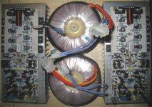
I received today from Plitron two 800W toroids providing +/-80V supplies under full load.
http://www.plitron.com/shopping/specs/508434.pdf
Under this circumstances, there is a small change is required in the OPS posted here:
http://www.diyaudio.com/forums/showthread.php?postid=1883792#post1883792
Q104, Q106, Q122, Q119 (2SC2240/2SA970) have to be replaced with higher breakdown voltage devices. I chosed 2SA1207/2SC2909 with a Vce>160V, but it's still at the very limit. You may want to replace all these with 2SA1381/2SC3503 (or the Fairchild KSA/KSC pair) having Vce>300V. Fortunately all these have the same pinout, so no changes are required in the PCB layout.
If you don't plan to go with such high supplies, and stay with worst case voltages less than +/-60V, 2SC2240/2SA970 with Vce>120V are your best bet.
Other devices like the 2N5551/2N5401 are pretty safe, they'll take easily over 160V.
I can confirm under 25ppm THD20 and IMD 19+20KHz at 600W (for a short time) into 4ohm ( 140Vpp ), mostly 2nd harmonic. Not sure if I'm measuring the amp, though, or some magnetic effect (peak currents through the supply lines are around 18A and average supply current is around 5.8A). Only the final construction will tell.
I will update the schematic to reflect this change.
stinius said:Maybe I’m wrong, but didn’t Scott somewhere talk about that AD are working on a online simulation service with better models, I wonder how they will implement the service with LT or PSPICE, I see that AD has a ADMultisim download, so maybe it will be linked to that. (And thereby would be out of interest)
It’s just a thought.
My ideas are generally vetoed. The op-amp models are macro models that vary in the quality of results. This is totally out of my control. It is true encripted HSPICE files with complete models are available under NDA for "serious" customers.
scott wurcer said:It is true encripted HSPICE files with complete models are available under NDA for "serious" customers.
Any idea why only for "serious" customers? How/what would harm AD to have these models available for everybody?
syn08 said:
Any idea why only for "serious" customers? How/what would harm AD to have these models available for everybody?
The lawyers say China whenever these things come up. Any encription can be cracked eventually. In fact I don't think it would matter one bit if we did this since the important processes are not available to them anyway.
The funny thing is the actual doing of this is turnkey by now and we probably pay more to have a macro-model made.
Re: An update
I see you put only about 400uF on output stage power supply rails. From my experience it is not enough exactly from magnetic fields point of view (even with 4 layers PCB, with very low power planes induction). You should see mainly even harmonics (second of course is strongest).
Also there is no sense to add the small shunt capacitors (C108-C111, C124-C127), because for modern Low-ESR capacitors (for example Panasonic FM) ESL is equal to induction of copper wire with length about distance between capacitor's pins and 1mm in dia (3-7nH). This paralleling sometimes rings on high frequencies (depends on C, ESL, ESR of capacitors).
What really wonders me, it's an output filter coil very close to the output stage. I thought it is a well known problem, that currents from output stage power lines can induce distorted current in it. As I see you take feedback only before the output filter, so these distortions will not be reduce by feedback. Are you sure you measure THD on the load, not in the point before filter ?
PS. Don't you have simulated loop gain and phase frequency responses graphics ?
Best regards, Nick
Hello syn08!Not sure if I'm measuring the amp, though, or some magnetic effect (peak currents through the supply lines are around 18A and average supply current is around 5.8A). Only the final construction will tell.
I see you put only about 400uF on output stage power supply rails. From my experience it is not enough exactly from magnetic fields point of view (even with 4 layers PCB, with very low power planes induction). You should see mainly even harmonics (second of course is strongest).
Also there is no sense to add the small shunt capacitors (C108-C111, C124-C127), because for modern Low-ESR capacitors (for example Panasonic FM) ESL is equal to induction of copper wire with length about distance between capacitor's pins and 1mm in dia (3-7nH). This paralleling sometimes rings on high frequencies (depends on C, ESL, ESR of capacitors).
What really wonders me, it's an output filter coil very close to the output stage. I thought it is a well known problem, that currents from output stage power lines can induce distorted current in it. As I see you take feedback only before the output filter, so these distortions will not be reduce by feedback. Are you sure you measure THD on the load, not in the point before filter ?
PS. Don't you have simulated loop gain and phase frequency responses graphics ?
Best regards, Nick
Dummy Load
Hello Syn08
Can I ask you about what sort of dummy load you use, is it a special construction.
Regards
Arthur
Hello Syn08
Can I ask you about what sort of dummy load you use, is it a special construction.
Regards
Arthur
Re: Re: An update
As I already said, indeed 2nd harmonics are dominant.
The idea of placing the big filter caps on the board was and still can be debated ad nauseam; for certain practical reasons, I am not supporting this solution. Of course it would be nice to resolve all high currents locally, but then how would you place 2 x 50,000uF/100V cans on the PCB? Paralleling 2 x 50 x 1000uF/100V? Those 100uF are only a last defense against potential local instabilities, aka decouplings.
I haven't noticed any ringings and those 100nF caps in parallel is something I always automatically add. They are probably an overkill, but I don't think they'll ever harm.
Yes, the output coil should be placed as much as possible away from the supply lines to avoid any magnetic couplings. I am sure this has a contribution to the increasing THD20 with the output power (reaching 25ppm @ 600W/4ohm). Though, to my experience, placing the output coil away from the OPS output is actually worse. One of the reasons is that the capacity between the load ground return wire (which always runs parallel to the load "hot" wire) loads the amp output before the output coil. Now this can potentially generate some significant ringing. It may not be the case for this amp, but generally I see placing the output coil away from the feedback connection as not a great idea.
I agree that the layout is critical in such an amp. I usually stick with what is known as working for me; I would love to have a chance to further experiment and optimize layouts, however this is a very expensive and time consuming process that I can't afford to go through. And after all, 25ppm at 600W output is something that can be certainly tolerated 😉 And certainly that number will go down after finishing the construction, with short supply wiring, etc...
I have measured the open loop gains for both the output stage loop and the global loop, using both the injection and the reference techiques described in the HP Application Note AN 243-2 and got pretty consistent results in between and with simulations, I'll post the results after cleaning up a little.
Mykola said:I see you put only about 400uF on output stage power supply rails. From my experience it is not enough exactly from magnetic fields point of view (even with 4 layers PCB, with very low power planes induction). You should see mainly even harmonics (second of course is strongest).
Also there is no sense to add the small shunt capacitors (C108-C111, C124-C127), because for modern Low-ESR capacitors (for example Panasonic FM) ESL is equal to induction of copper wire with length about distance between capacitor's pins and 1mm in dia (3-7nH). This paralleling sometimes rings on high frequencies (depends on C, ESL, ESR of capacitors).
What really wonders me, it's an output filter coil very close to the output stage. I thought it is a well known problem, that currents from output stage power lines can induce distorted current in it. As I see you take feedback only before the output filter, so these distortions will not be reduce by feedback. Are you sure you measure THD on the load, not in the point before filter ?
PS. Don't you have simulated loop gain and phase frequency responses graphics ?
As I already said, indeed 2nd harmonics are dominant.
The idea of placing the big filter caps on the board was and still can be debated ad nauseam; for certain practical reasons, I am not supporting this solution. Of course it would be nice to resolve all high currents locally, but then how would you place 2 x 50,000uF/100V cans on the PCB? Paralleling 2 x 50 x 1000uF/100V? Those 100uF are only a last defense against potential local instabilities, aka decouplings.
I haven't noticed any ringings and those 100nF caps in parallel is something I always automatically add. They are probably an overkill, but I don't think they'll ever harm.
Yes, the output coil should be placed as much as possible away from the supply lines to avoid any magnetic couplings. I am sure this has a contribution to the increasing THD20 with the output power (reaching 25ppm @ 600W/4ohm). Though, to my experience, placing the output coil away from the OPS output is actually worse. One of the reasons is that the capacity between the load ground return wire (which always runs parallel to the load "hot" wire) loads the amp output before the output coil. Now this can potentially generate some significant ringing. It may not be the case for this amp, but generally I see placing the output coil away from the feedback connection as not a great idea.
I agree that the layout is critical in such an amp. I usually stick with what is known as working for me; I would love to have a chance to further experiment and optimize layouts, however this is a very expensive and time consuming process that I can't afford to go through. And after all, 25ppm at 600W output is something that can be certainly tolerated 😉 And certainly that number will go down after finishing the construction, with short supply wiring, etc...
I have measured the open loop gains for both the output stage loop and the global loop, using both the injection and the reference techiques described in the HP Application Note AN 243-2 and got pretty consistent results in between and with simulations, I'll post the results after cleaning up a little.
Re: Dummy Load
For resistive loads, I got some time ago from a Mouser sale a bunch of Dale RH-50 16ohm/50W resistors. I installed 16 of them on a big heatsink I got from EBay and I'm hard wiring all kind of loads when testing an amp.
For reactive loads, I have a small stock of mylar 1-10uF/250V caps out of which I'm happily occasionally exploding some when testing at full power 😉 These, and some small (0.22-2.2ohm) power resistors in series, will do a decent worst case reactive loads. I'm no longer a fan of speaker simulated loads, simply because one cannot test for all possible RLC combinations that real speakers may have.
PHEONIX said:Can I ask you about what sort of dummy load you use, is it a special construction.
For resistive loads, I got some time ago from a Mouser sale a bunch of Dale RH-50 16ohm/50W resistors. I installed 16 of them on a big heatsink I got from EBay and I'm hard wiring all kind of loads when testing an amp.
For reactive loads, I have a small stock of mylar 1-10uF/250V caps out of which I'm happily occasionally exploding some when testing at full power 😉 These, and some small (0.22-2.2ohm) power resistors in series, will do a decent worst case reactive loads. I'm no longer a fan of speaker simulated loads, simply because one cannot test for all possible RLC combinations that real speakers may have.
'can potentially generate some significant ringing'
 I wonder how large might the capacitance between those two wires be. I guess something between 10...100pF. An amplifier that can't handle such a low capacitance and starts ringing is certainly not the most stable amp on earth - to put it mildly.
Anyhow, placing the output coil on the OPS-PCB or in the direct vicinity of other metal objects is not a good idea.
syn08 said:[snip]
Yes, the output coil should be placed as much as possible away from the supply lines to avoid any magnetic couplings. I am sure this has a contribution to the increasing THD20 with the output power (reaching 25ppm @ 600W/4ohm). Though, to my experience, placing the output coil away from the OPS output is actually worse. One of the reasons is that the capacity between the load ground return wire (which always runs parallel to the load "hot" wire) loads the amp output before the output coil. Now this can potentially generate some significant ringing. It may not be the case for this amp, but generally I see placing the output coil away from the feedback connection as not a great idea.
[snip]
I wonder how large might the capacitance between those two wires be. I guess something between 10...100pF. An amplifier that can't handle such a low capacitance and starts ringing is certainly not the most stable amp on earth - to put it mildly.Anyhow, placing the output coil on the OPS-PCB or in the direct vicinity of other metal objects is not a good idea.
Re: Re: Re: An update
I think 2 x 4...8 x 4700uF may be enough.Of course it would be nice to resolve all high currents locally, but then how would you place 2 x 50,000uF/100V cans on the PCB? Paralleling 2 x 50 x 1000uF/100V?
I guess it's very unlikely (in appropriate design). But if you like to leave it on OPS-PCB, I think you may consider the idea of putting the output filter in the feedback loop...Now this can potentially generate some significant ringing. It may not be the case for this amp, but generally I see placing the output coil away from the feedback connection as not a great idea.
how about air core toroidal output inductor winding to cut some external field coupling? - still need surrounding air space but it should be less of an antenna than the cylindrical coil
Hi,syn08 said:Two channels on 0.4 C/W heatsinks and two monster toroids going to the 5RU chassis, for 2 x 400W/4ohm.
what is the quiescent power (Pq)?
What is the predicted heatsink temperature (Ts)
- Status
- Not open for further replies.
- Home
- Amplifiers
- Solid State
- YAP power amp revisited, now at v2.1