About the noise recordings: As the transformer in the Xvive, that converts the mkh-416 signal to single ended, has not been removed yet, it adds about 6dB to the MKH-416 recording.
It's a 1:1 transformer, so the voltage across the secondary is supposed to be roughly equal to the voltage across the primary. Of course it converts from differential to single-ended, so measured with respect to ground, the secondary voltage is twice as large as the voltage from each primary terminal to ground. Is that where your 6 dB comes from?
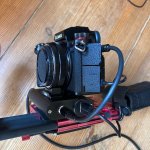
The other recordings were made with a shorted 3.5mm plug inserted inti the cameras mic input. The Cabinet of the Xvive is metal, probably die cast aluminium
Clear, thanks!
Yep! When I recorded the sweep earlier in this thread, I did raise the recordings without the Xvive/transformer inserted so that the peak is equal.It's a 1:1 transformer, so the voltage across the secondary is supposed to be roughly equal to the voltage across the primary. Of course it converts from differential to single-ended, so measured with respect to ground, the secondary voltage is twice as large as the voltage from each primary terminal to ground. Is that where your 6 dB comes from?
to the recording with the Xvive inserted. I think it was about 5-6dB. If you like, I can recheck tonight, how much dB the transfromer adds to the MKH-416 self noise.
Maybe also important: Do we keep the circuit single ended or balanced? Because there is conversion from balanced to single ended
anyway in an adapter box , minus to GND and voltage divider, R1 270ohms R2 160ohms. This adapter box will be always needed
so that I can alternitavely plug in a field mixer. All the best, Salar
Last edited:
That only works for floating balanced outputs, that is, outputs with a high common-mode impedance. My simple two op-amp circuits have a low common-mode output impedance. You are essentially using the positive and shorting the negative output then.
Was that adapter box also in the signal path when you recorded with the MKH-416?
Was that adapter box also in the signal path when you recorded with the MKH-416?
Yes always.
It is fixed beneath the camera and adapts from Mono Balanced XLR / Din to single ended "Stereo",
(3.5mm plug) using the voltage divider to attenuate -9dB on the right channel.
So the right channel acts as safety backup when clipping occurs.
It is fixed beneath the camera and adapts from Mono Balanced XLR / Din to single ended "Stereo",
(3.5mm plug) using the voltage divider to attenuate -9dB on the right channel.
So the right channel acts as safety backup when clipping occurs.
Attachments

Last edited:
Theoretically 352.0740309 ohm when the voltage divider is loaded with 2200 ohm and there is another 2200 ohm connected to its input. With two 5.4 uF capacitors that are effectively in series, the cut-off frequency should be 167.425797 Hz. With only one channel and no attenuator, you would have had 5.4 uF/2 with 2200 ohm -> 26.79376146 Hz.
Anyway, with big electrolytic capacitors you still had bass loss due to the camera.
Anyway, with big electrolytic capacitors you still had bass loss due to the camera.
Regarding the gain and noise, I got these figures from your recordings, all RMS levels in dB with respect to the RMS value of a sine wave that drives the ADC to the edge of clipping.
Line:
Minimum gain (-12 dB): -82.17 dB(A) left, -82.3 dB(A) right
Maximum gain (+6 dB): -81.22 dB(A) left, -81.08 dB(A) right
Microphone input, shorted:
Minimum gain (-12 dB): -79.36 dB(A) left, -79.27 dB(A) right
Maximum gain (+6 dB): -64.76 dB(A) left, -64.66 dB(A) right
MKH-416:
Minimum gain (-12 dB): -76.25 dB(A) left, -78.46 dB(A) right
Maximum gain (+6 dB): -59.8 dB(A) left, -63.05 dB(A) right
MKH-416 with the microphone input noise subtracted:
Minimum gain (-12 dB): -79.16 dB(A) left, -86.15 dB(A) right
Maximum gain (+6 dB): -61.47 dB(A) left, -68.14 dB(A) right
As you already noted, the noise floor of the line input doesn't change much with the gain setting, when you look at it with respect to the maximum level: 1.05 dB left and 1.22 dB right. There is therefore no reason not to record with the +6 dB gain setting when you use the line input.
At maximum gain, the noise of the microphone with the noise of the built-in microphone amplifier subtracted is -61.47 dB(A) - (-81.22 dB(A)) = 19.75 dB above the noise of the line input. 5.87 dB suffices when you want to keep the noise increase due to the line input noise below 1 dB, or 0.02 dB if you are willing to accept a 3 dB increase due to the line input noise.
The setting that you are actually using now (-12 dB), amplifies the microphone's noise to -79.16 dB(A) - (-82.17 dB(A)) = 3.01 dB above the line input noise, meaning that the microphone noise and line input noise together are 1.76 dB above the microphone's noise. Taking this as the criterion when the line input gain is set to maximum, the gain of the microphone amplifier could therefore be reduced by 19.75 dB - 3.01 dB = 16.74 dB. Instead of 45 dB voltage gain (from differential input voltage to single-ended output voltage, 6 dB more when you measure voltages with respect to ground), the gain would then be:
28.26 dB from the differential input voltage to the single-ended output voltage.
This circuit should do. It would be nice if you could increase the impedance of your voltage divider somewhat, that makes it easier to drive for U1A and you can then use a smaller value for C4.
Strange: We have the bass loss only when the input menu of the camera is switched to to Mic /-55dbVThis does explain some of the bass loss you had, the load impedance is quite low.
We do not have it when the input menu of the camera is switched to to Line /-10dbV.
See the files I sent in post #43: https://filetransfer.io/data-package/MwUjrZur#link
Values of the voltage divider were wrong.Theoretically 352.0740309 ohm when the voltage divider is loaded with 2200 ohm and there is another 2200 ohm connected to its input. With two 5.4 uF capacitors that are effectively in series, the cut-off frequency should be 167.425797 Hz. With only one channel and no attenuator, you would have had 5.4 uF/2 with 2200 ohm -> 26.79376146 Hz.
Anyway, with big electrolytic capacitors you still had bass loss due to the camera.
I did put in 390Ω/240Ω.
But I do not understand in the quote above you refer to the circuit like it is now,
without the micpreamp you propose, correct?
Anyway, this is what your circuit or a field mixer will always see:
Attachments

I was referring to when the bass loss was still worse with the phantom supply inserted than without the phantom supply inserted. As far as I recall, the 5.4 uF capacitors did not fully solve that, but the 94 uF capacitors did. I never understood that until now. It is indeed not applicable with the proposed external microphone amplifier, as long as the output coupling capacitor of that microphone amplifier is big enough.
Marcel, many thanks!
As we know i put into the Xvive a transformer for "buffering" the MKH-416 signal
when converting from balanced to unbalanced.
But the conversion happens after the transformer, in the box pictured in post#84.
I did record a 1kHz testtone with and without the Xvive and the transformer in the signal path.
Looks like transformer adds about 5dB.
So the file
"MIC_LEVEL-55dbV_MKH-416_MUTE-12-9-6-3-0+3+6"
should have about 5dB less.
I assume, theoretically, without the transformer, the MKH-416 is:
Minimum gain (-12 dB): -81.25 dB(A) left, -83.46 dB(A) right
Maximum gain (+6 dB): -64.8 dB(A) left, -68.05 dB(A) right
So instead of 28.26db, the desired gain should be about 34dB?
Here is the testtone:
https://filetransfer.io/data-package/jhWRQRod#link
All the best,
Salar
Hi Salar,
A 1:1 transformer is not supposed to have any gain. I suspect the source you used for measuring that behaves as the lower part of this sketch:

If it does, you shorted the lower half of the signal source when measuring without transformer, halving the signal. The transformer behaves as a floating source, so then you don't short half the signal.
Regards,
Marcel
A 1:1 transformer is not supposed to have any gain. I suspect the source you used for measuring that behaves as the lower part of this sketch:
If it does, you shorted the lower half of the signal source when measuring without transformer, halving the signal. The transformer behaves as a floating source, so then you don't short half the signal.
Regards,
Marcel
Dear Marcel,If it does, you shorted the lower half of the signal source when measuring without transformer, halving the signal. The transformer behaves as a floating source, so then you don't short half the signal.
This is what the adapter box does, when being connected to XLR, see the graphics in post#89.
"R_Innenwiderstand" "160" on the Left is not part of the circuit, it means the output impedance of the field mixer.
So it is the other way round?
The "true" noise level is the MKH416 with floating balanced input, as measured in post#75?
Perfect: Last questions:
-Is 28.26dB the theoretical gain or the practical gain of the circuit?
-To raise or lower the gain, I need to play with resistors 1 / 2 / 7?
-Is C4 an unavoidable must?
-C4 and C6 can have 5V? (limited Space)
-What would you want as voltage divider instead of 390Ω / 240Ω in the adapter box.
It was chosen because back then a technician told me it better sinks noise.
-If the math can be done:
Recording a Interview, Speech is about 60dB.
This would equal which record level on the S5?
The S5 has a settable gain range of only 18dB, but recording mono with the right channel as safety
at -9dB I have 27dB - well, so to say.
This is why I would like to go a tad hotter, in order to use the full 16 bit resolution
Rock concerts will not be the norm, but Interviews.
All the best,
Salar
You can adjust the gain by changing R4, R5 and R2. The gain is proportional to R4 = R5. Besides, R2 = R1 + R4 rounded to the nearest standard value.
You could use a ceramic multilayer X5R SMD capacitor for C6, but preferably not for capacitor C4.
6.3 V working voltage is enough, or 5 V if the supply remains below 5 V.
You could use a ceramic multilayer X5R SMD capacitor for C6, but preferably not for capacitor C4.
6.3 V working voltage is enough, or 5 V if the supply remains below 5 V.
Last edited:
Thanks,
so raising the gain of R4, R5 and R2 from 15k to 18k will raise output?
Nothing else to deal with?
"hat is the gain of your circuit pictured in Post #88 with 15 k?
I will use an adaperboard, so C6 does not need to be SMD.
Again, is C4 a must?
Just got a mail that the opamp arrived.
I have on only two hours left to buy the parts pof the circuit,
otherwise I will be blocked until Tuesday because of 1rst of Mai...
With the indicated values, the gain of the circuit of post #88 is close to 28.26 dB, the gain proposed in post #88.
Regarding leaving out C4: if your camera uses the same connector for line input and microphone input with PiP, chances are it is designed to handle a DC voltage of a few volts. Leaving out C4 will then only lead to a somewhat increased supply current, no other ill effects.
Regarding leaving out C4: if your camera uses the same connector for line input and microphone input with PiP, chances are it is designed to handle a DC voltage of a few volts. Leaving out C4 will then only lead to a somewhat increased supply current, no other ill effects.
You can adjust the gain by changing R4, R5 and R2. The gain is proportional to R4 = R5. Besides, R2 = R1 + R4 rounded to the nearest standard value.
Many thanks, but I am not diy-ing because of the fun of mathematics - which I am bad at -
but because I cannot find a readymade solution.
Can you give me values to achieve a gain between 33 and 36 dB?
All the best, Salar
What gain settings do you use with the present circuit? Always -12 dB or sometimes louder? With the circuit of post #88, you should get essentially the same sound with the line input gain set to +6 dB as you now get with the microphone input gain set to -12 dB, except for the bass roll-off.
Dear Marcel,
-12 dB.
But -9 dB to -6 dB would be also ok.
Space will be very tight, I will have to put the circuit on two boards,
maybe I can stack them. And the outer pads should not be used to prevent
short circuit to the case of the Xvive. Got a wrong adapter for the opamp,
need to buy a new one, so I can start soldering not before Tuesday...
I would like to put 220µF/6.3V or 100uF/16V after the output of LME49721.
Is 220µF overkill? Is 390Ω/240Ω (See post#89) ok for you as voltage divider?
All the best, Salar
- Home
- Live Sound
- Instruments and Amps
- Xvive 48V Phantom Power supply acts a high pass