I was thinking about an unbalanced design that refers its output voltage to the receiving ground. If my calculations are correct, this should more or less do the trick (see R8 and the funny way it is connected):

It has the advantage that any voltage drop across the shield of the long cable doesn't get superimposed on the signal, because the wire that connects pin 3 senses the receiving ground.
The version with the transformer, which would be more effective in suppressing interference picked up by the cabling, would be

In either case, the values of resistors R2, R4 and R5 have to be changed according to the desired gain, as discussed before.
It has the advantage that any voltage drop across the shield of the long cable doesn't get superimposed on the signal, because the wire that connects pin 3 senses the receiving ground.
The version with the transformer, which would be more effective in suppressing interference picked up by the cabling, would be
In either case, the values of resistors R2, R4 and R5 have to be changed according to the desired gain, as discussed before.
Great! C4 with the transformer might be tricky, because of the limited space. Do I get this correct:
The balanced design is hard to realize because the negative supply is missing? Because the voltage divider of R9/R10 can only
feed the positive inputs of the LME49721? All the best, Salar
The balanced design is hard to realize because the negative supply is missing? Because the voltage divider of R9/R10 can only
feed the positive inputs of the LME49721? All the best, Salar
Actually, at frequencies of 120 Hz and higher, the version with transformer will have twice the headroom at a given gain when you make it like this:

If you can get small bipolar electrolytic capacitors, use one of those for C4, otherwise a normal electrolytic capacitor (or two with twice the value in antiseries, but that won't fit at all).
For a given gain, the value of R5 has to be about half what it was for the previous circuit. R1 has to get the same value as R5, there is no need to change R2 or R4 when you want to adjust the gain.
When you build something like this without transformer and ground the negative output, it won't work properly, because the bottom op-amp's output is more or less shorted.
Supergreat! No need for a electrolytic capacitor for the bottom opamps output? Is bipolar a must? Without transformer, would be resistors at the output sufficient? All the best, Salar
I have already bought the parts and would experiment with 39k for R5 and R1.
For convenience, as I would need to buy 15k:
Can I use 39K also for R2 and R4? Again, Bipolar is a must - because of the transformer?
What I have now is polar 220µF/6.3V or 100µF/25V
If I´ll need to buy a bipolar anyway today, then I am free for choosing R1/R2, R4/R5.
For convenience, as I would need to buy 15k:
Can I use 39K also for R2 and R4? Again, Bipolar is a must - because of the transformer?
What I have now is polar 220µF/6.3V or 100µF/25V
If I´ll need to buy a bipolar anyway today, then I am free for choosing R1/R2, R4/R5.
Last edited:
Can I use 39K also for R2 and R4?
Yes.
Again, Bipolar is a must - because of the transformer?
What I have now is polar 220µF/6.3V or 100µF/25V
If I´ll need to buy a bipolar anyway today, then I am free for choosing R1/R2, R4/R5.
A polar electrolytic capacitor should also work. It will be subjected to voltages in both polarities, but ordinary electrolytic capacitors (polarized aluminium electrolytic capacitors) can handle that as long as the reverse voltage doesn't exceed 1 V to 1.5 V. Don't use a tantalum capacitor, as those are far worse at handling small reverse voltages.
Last edited:
Just a trick to be able to quote your message. There must be other ways to do that, but this works.??? 🙂
Aha. So, how much reverse voltage
the electrolytic can bear is independend from its voltage rating? So a 6.3V rated one withstands 1.5V maximum as good as a 400V rated one?
the electrolytic can bear is independend from its voltage rating? So a 6.3V rated one withstands 1.5V maximum as good as a 400V rated one?
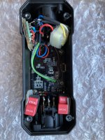
WORKS! 😀 "micverstg" MANY THANKS! And I am trained now in soldering bugs.
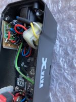
Everything fitted on one board, the transformer and Cap were hardwired.
I chose 39K, but at the -12 dB recording setting, the opamp clips just about
3dB earlier before the camera would clip. I will set two another 39k in parallel
with R1 and R5 (easier with SMD) the following days to reduce gain...?
R2 and R4 are buried now under wires, will not be able to change them.
The voltage divider has not been changed yet, 390Ω/240Ω
but I assume it will not put too much load to the transformer?
Unfortunately, it is now Phantom Power only, as the old setup was passive.
So no clean Testtones to record without the mic involved...
Great that it works! There is no need to change R2 and R4, you can leave them both at the present values no matter what gain you want.
BTW what is the function of R2 and R4 in Version G? In the earlier versions A-F they were related to R1 and R5, correct?
They bias the op-amp inputs at a suitable DC voltage. They are not related to the gain setting in any way in version G, unlike earlier versions. Their value isn't critical; anything from 10 kohm to 100 kohm will work fine, as long as they both have the same value.
Perfect. I did solder one extra 39k resistor in parallel for R1 and R5, so it is about 19.5k,
I assume about 30dB gain.
Had an appointment and had to leave in a hurry. I assume it is normal that one
can't measure the resistance of installed feedback resistors as the total
impedance of input and output of the opamp are too high?
I assume about 30dB gain.
Had an appointment and had to leave in a hurry. I assume it is normal that one
can't measure the resistance of installed feedback resistors as the total
impedance of input and output of the opamp are too high?
Uhm... unfortunately something happened after soldering a second SMD 39k
resistor to the exising R1 and R5 to halve resistance and lower gain.
The clipping still happens as early as before though I must have gained some 6dB.
Also with a loud tone, gain would suddenly jump higher.
I thought maybe a cold soldering joint at the R1 and R5 pairs, resoldered them.
The clipping point did not change. The "jump" to higher gain is gone,
but now, when clipping, the circuitry "shuts off". Mute.
Tested with the pcb inside and outside the casing to test for shorts, no difference.
Peaks like snipping your fingers close to the mic do nothing unless you do it quickly -
then the mic preamp shuts off.
Turning the ciruitry off and on again brings the sound back to life - until the next
loud sound shuts it off.
Any ideas? Yesterday, with the higher gain -
39kΩ instead of 19.5KΩ now at R1 / R5 - the problems were not there.
C1 had to suffer some heat but what could trigger a bypass capacitor to short?
And in case I did not fry the Opamp (fortunately I have two), what else could be the reason?
BTW this is how it looked this morning, before I changed the feedback resistors,
one can be clearly seen....
Attachments
Last edited:
Maybe R2 or R4 or both not making any contact. The positive inputs of the op-amp are then not properly biased and can float anywhere. When the sound is loud, rectifying effects in the input clamping diodes may then shift the DC level.
What did you mean by: "I assume it is normal that one can't measure the resistance of installed feedback resistors as the total impedance of input and output of the opamp are too high?" What exactly did you try to measure and what was the result?
What did you mean by: "I assume it is normal that one can't measure the resistance of installed feedback resistors as the total impedance of input and output of the opamp are too high?" What exactly did you try to measure and what was the result?
No, I resoldered many times,
don‘t think so.
But as rhe opamp is on an adapter board that has the SOIC part turned 90 degrees- the trace of input 5 runs close to 6+7.
Maybe protective paint molded
and rher is some contact.
I could simply not measure resistance when R1 and R5were istalled, too high for the 200k range of the voltmeter, i guess this is normal. I had to leave really quickly and did not measure in higher settings.
Could you measure the supply voltage, the DC voltages at the outputs of the op-amps and the DC voltages (with respect to ground) at the inputs of the microphone amplifier circuit while it is on? All DC bias voltages are supposed to be close to half the supply voltage. You may see some difference between the output DC voltages, differences greater than 0.15 V are suspicious.
- Home
- Live Sound
- Instruments and Amps
- Xvive 48V Phantom Power supply acts a high pass