Yep, I got more.
I see the new BOM recommends 2 1000uF 16v OSCON for low impedance, is this now preferred to the 2200uF Nichicon KA as well?
I've found where I got the 10uF Silmic on the inputs, it's a BOM from Dec 17, 2017. Is this completely outdated now?
Pocket Class A Headamp BOMNHB Caps Version KA-Silmic v2 Dec 17, 2017Label on - Pastebin.com
The output cap brand and type are subjective - like all capacitors. The value of 2000uF ot 2200uF is a good idea if you are driving 16ohm headphones.
The 10uF Silmic input is again, subjective. It’s not obsolete and in my opinion, the Silmic sounds really smooth and I would keep it. The 2.2uF Wima MKS 50v is very neutral and not much can be found fault wise.
Hope that helps.
The 10uF Silmic input is again, subjective. It’s not obsolete and in my opinion, the Silmic sounds really smooth and I would keep it. The 2.2uF Wima MKS 50v is very neutral and not much can be found fault wise.
Hope that helps.
Yes of course, thanks.
I'll try the Wimas on the inputs I guess. Have you tried higher values than 2.2uF?
Also how critical is the 117.5R sweetspot for R7? Would 120R make a difference?
I'll try the Wimas on the inputs I guess. Have you tried higher values than 2.2uF?
Also how critical is the 117.5R sweetspot for R7? Would 120R make a difference?
2.2uF is the minimum to get bass down to 10Hz. Tried bigger with 10uF Silmic but not enough space for other films.
117.5 is just convenient from parallel of 4x 470ohms. 120ohms is fine it will change bias current a small amount.
117.5 is just convenient from parallel of 4x 470ohms. 120ohms is fine it will change bias current a small amount.
Thanks again.
I haven't seen it mentioned elsewhere so thought I'd mention that I've been using Panasonic FS for the rails, they are miniaturized FR (seem to have the same profile but I could be wrong). 2200uF can fit if you forego the JST connector (solder connections from the SMD side) and are rated for 105c (vs 85c for Nichicon VK). Although a lot of the ones I have test low (on my shitty multimeter) around 2100uF.
I haven't seen it mentioned elsewhere so thought I'd mention that I've been using Panasonic FS for the rails, they are miniaturized FR (seem to have the same profile but I could be wrong). 2200uF can fit if you forego the JST connector (solder connections from the SMD side) and are rated for 105c (vs 85c for Nichicon VK). Although a lot of the ones I have test low (on my shitty multimeter) around 2100uF.
Last edited by a moderator:
X, do you know if new transistors solved that guy's volume issues on one side?
My right is so low I thought it wasn't working at all. I looked the board up and down and can't see anything wrong, I did discover an unsoldered R5 but on the left and that didn't do anything.
I do have a bunch of bodges but everything checked out. Pulled the plating from 5 through holes desoldering but fixed it (soundly I believe) soldering 2 strands of 18awg to the trace and running them through the holes, and it all checked out.
Identical voltages throughout the circuit best as I can tell.
Only thing I don't have connected is pin 3 on the output jack but that isn't connected anyway...right...?
Hi Jebivitar,
I'm not sure what you are asking? If R5 was unsoldered, it should not have worked, but since you resoldered it and it still doesn not work, that was not the problem.
Some things to look for when debugging: measure the voltage at each pin of the output MOSFETs while the amp is powered and report back.
Pin 1 tells you if the JFET stage is working, pin 2 tells you if you are getting power to the MOSFET, and pin 3 tells you if the MOSFET is working.
Pin 2 should be same as Vcc battery or about 16v to 18v depending on battery life and type.
Pin 3 should be about 1/2 of pin 2, typically a little lower. If it shows 6.5v to 7.5v, the amp is working correctly and you should get music.
Pin 1 should be about 9v to 10v If it is way, off there is either a cold solder joint aroun one of the resistors above or below the JFET.
Hope that helps.
Last edited:
I was asking if Pin 3 of the jack should be connected to anything. R5 was soldered on one side but not on the other.
I've sorted the low power on the right issue...it was the input headphone cable...
But now I get pretty loud static/noise/hiss on the left, even without input, and I'm almost certain that was not there just earlier, I guess I borked something troubleshooting.
And those are not the values I'm getting...
M1A
S 12.25
D 17.94
G 13.75
M1B
S 9.92
D 17.94
G 11.41
I have R4 at 51R and R5 at 220R per your suggestion way back when, and R7 at 120R.
I matched these FETs to 2 decimal places two years ago....hmmm...
Last edited by a moderator:
Desoldered the FETs and 3 tested way off their original measurements (both ZVNs were bad) in a matching circuit. The SMM02040C2400FB300 resistors I'm using for R7 tested OK out of circuit.
Tested some of the FETs in my stash and they were the same as the 2 year old original measurements so I wonder what damaged them, I'm not an expert solderer but I'm not a complete novice either...
Of course the chips could have been damaged desoldering but I believe I got techniques those down - unlike the pot and jack which I definitely do not have down - for the SOT-223-3 I melt a little bismuth solder into the tab to lower the melt temperature and then run a wide tip across the three legs and it slides right off.
Is there anything else I can measure with the FETs (and R7 too I guess) not in place?
Your numbers are all way off on M2. M1 looks ok, but voltage at S looks a bit high. Looks like damaged components? Be careful with ESD. Use a wrist strap connected to a large metal object or house “earth ground”. Don’t wear sweaters, polyester, wool, etc while working. Discharge your fingers on nearby grounded niece before touching.
JFETs are pretty sturdy. The MOSFETs can be zapped easily.
JFETs are pretty sturdy. The MOSFETs can be zapped easily.
After killing the JFET I've been using in my matching circuit, I think I've got to the bottom of the dead transistors.
Some time ago I caught my iron in some plastic and it melted all over the metal piece that holds down the tip. I transplanted a replacement from a clone iron, that as it turns out is a fraction of a millimetre longer and doesn't hold down the tip perfectly. That metal piece of course also grounds the tip.
I was still getting some funky measurements during my last round of troubleshooting so I'm sure I'll have more silly things to ask.
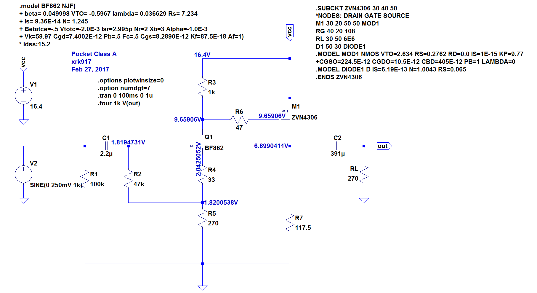
X, are you able to share your LTspice sim? Searched the thread and couldn't find one, but also didn't see anyone ask...
I see Vcc in the updated sim is 16.4v, whereas it used to be 18v.
Curious why this change was made? Can't search the thread for such a short string unfortunately.
Curious why this change was made? Can't search the thread for such a short string unfortunately.
Two EBL Li-ion rechargeable batteries are 16.4v fully charged. Not 18v despite being called “9v” batteries. The “OK” brand has lower capacity but built in DC-DC converter for true 9v output.
I have this up in LTSpice and have some questions/observations.
1. A long time ago, you recommended R3 820Ω and R5 220Ω when I asked how to get a bump in volume; even longer ago someone only had 200Ω and 330Ω resistors and you recommended he use 200Ω for R5. I'm curious why not go bigger at R5? Bumping it to 330Ω reduces THD from .0147% to .005% without much change anywhere except around the JFET to my completely untrained eyes, and the small voltage bump there seems innocuous.
2. Increasing temperature of sim seems to have pretty significant impact, e.g., increasing it to 55c (.temp 55), will decrease Vout from 8.43v to 7.98v, decrease the current going through R3 from .70mA to .67mA, and decrease THD from .0142% to .002%.
3. You often suggest to get the R3 bias to ~50mA - what are the consequences of higher bias current going through R3? Say ~65mA?
It's all a balancing game with the resistor settings. Here are the guidelines if you want to roll your own resistor settings:
1. aim for setting the current through the JFET to be about 70% of its Idss - but this is flexible - ok to be lower, but don't run near 100% of Idss.
2. aim to set the voltage at the MOSFET source to be about 1/2 of Vcc and set the current through the MOSFET to be about 50mA (low side) to 70mA (high side). If using lower impedance headphones, aim for higher current. The limit is battery drain and thermal dissipation. 70mA x 8v drop = 640mW or 1.28W for both channels and that's pretty toasty.
3. aim for circa 0.02% to 0.06% THD but dominant 2nd order and about -10dB to -15dB less third harmonic distortion and hopefully no higher orders or monotonically descending higher orders. 0.05% THD and dominant second order sounds the best to many ears - and is one reason why SET tube amps are so popular.
4. Adjust the ratio of R3/(R4+R5) to get the gain you want - and typically 3x (9.5dB) to 4x (12dB) is a good range.
5. Adjust the bias current through the source resistors R7 (4x) such that dissipation is within rated thermal of 4x 1/8w or 1/2w total.
65mA is perfectly good and it is about where I typically run it. Although 70% of Idss is good to aim for, I have tried 110uA bia through the JFET and it sounds good there to - and perhaps has a nicer resolving sound.
In the end, try what sounds good to your ear. My formula is that 0.05% THD and dominant H2 vs H3 sounds good to most people and most music.
It's all a balancing game with the resistor settings. Here are the guidelines if you want to roll your own resistor settings:
1. aim for setting the current through the JFET to be about 70% of its Idss - but this is flexible - ok to be lower, but don't run near 100% of Idss.
2. aim to set the voltage at the MOSFET source to be about 1/2 of Vcc and set the current through the MOSFET to be about 50mA (low side) to 70mA (high side). If using lower impedance headphones, aim for higher current. The limit is battery drain and thermal dissipation. 70mA x 8v drop = 640mW or 1.28W for both channels and that's pretty toasty.
3. aim for circa 0.02% to 0.06% THD but dominant 2nd order and about -10dB to -15dB less third harmonic distortion and hopefully no higher orders or monotonically descending higher orders. 0.05% THD and dominant second order sounds the best to many ears - and is one reason why SET tube amps are so popular.
4. Adjust the ratio of R3/(R4+R5) to get the gain you want - and typically 3x (9.5dB) to 4x (12dB) is a good range.
5. Adjust the bias current through the source resistors R7 (4x) such that dissipation is within rated thermal of 4x 1/8w or 1/2w total.
65mA is perfectly good and it is about where I typically run it. Although 70% of Idss is good to aim for, I have tried 110uA bia through the JFET and it sounds good there to - and perhaps has a nicer resolving sound.
In the end, try what sounds good to your ear. My formula is that 0.05% THD and dominant H2 vs H3 sounds good to most people and most music.
I just ordered your PCA daughter board, for use in M2x. Is the circuit diagram set for these goals? Any other suggestions? I just ordered the cards and parts yesterday. I built the Yakuin boards, but kept unseating something or other as I try to bolt them on. I thought they were a bit bass heavy, but that might just be the higher gain over the standard M2x cards. I might build a new set one day, and mount more parts on the bottom, avoiding the nut placement locations. Building Mark’s 2 new cards this weekend. Lastly, are there any of the SMD version Melbourne cards left?
Signed - M2x daughter board junky
The Yarra/M2X format PCA daughterboards do follow this general process of setting resistors. The PCA board is probably closer to the DCA as it has higher bias current. In the Yarra thread are the setpoints for the resistors and it depends on the JFET used (2SK209GR/BL vs 2SK170BL, vs BF862).
Note that to mount these Yarra format boards on the M2X will need to use a ground connection from the daughterboard to the main amp. The stock M2X daughterboards do not have a ground connection.
Yes, I have more SMT Melbourne boards.
Note that to mount these Yarra format boards on the M2X will need to use a ground connection from the daughterboard to the main amp. The stock M2X daughterboards do not have a ground connection.
Yes, I have more SMT Melbourne boards.
Last edited:
Thanks. Seems clear(ish) on a third read. I have some reading to do on harmonics.
Unrelated to that. Do you know if it's possible to get LTspice to sim the cap multiplier circuit? My attempts have been unsuccessful.
Unrelated to that. Do you know if it's possible to get LTspice to sim the cap multiplier circuit? My attempts have been unsuccessful.
Last edited by a moderator:
Yes, I have seen Jhofland do it. Look in SLB thread. It’s nothing special - just wire it like it is shown. The trick is to apply a sine wave ripple into it as source and see how much ripple comes out. There needs to be an appropriate resistive load.
- Home
- Group Buys
- xrk971 Pocket Class A Headamp GB