What you built is a frequency divider. Its one example of what I was talking about.
Regarding what rfbrw was talking about, it applies to Amanero USB boards. XMOS is a different system with different types of chips. IIUC, XMOS chips are flashed using a hardware JTAG interface. Its just most USB boards aren't designed with the necessary connector support. Also, you would a XMOS chip program complier from XMOS. It can be downloaded and the manuals read, but using it may take some time depending on your programming skills.
Regarding what rfbrw was talking about, it applies to Amanero USB boards. XMOS is a different system with different types of chips. IIUC, XMOS chips are flashed using a hardware JTAG interface. Its just most USB boards aren't designed with the necessary connector support. Also, you would a XMOS chip program complier from XMOS. It can be downloaded and the manuals read, but using it may take some time depending on your programming skills.
Last edited:

Unsure about rfbrw's comments. rfbrw knew I had an XMOS-based adapter from that thread. Very luna.What you built is a frequency divider. Its one example of what I was talking about.
Regarding what rfbrw was talking about, it applies to Amanero USB boards. XMOS is a different system with different types of chips.
IAC, I may have been wrong that I built that Tent divider, tho' I might have (but did not use it). I did a some research about /2 -- many moons ago -- and found the Tom Napier 1998 EDN version as the "best".
Attached below.
Attachments
I have used ICS542, but you may need an inverter too, such as SN74LVC1G04. Don't forget bypass caps and series termination resistors as well...
Would also recommend designing a small board with a ground plane and a local 3.3v regulator. Probably doesn't have to be a super regulator though. Not the kind of thing to build on Vero Board, unless maybe you like a lot of jitter in your clocks.
Would also recommend designing a small board with a ground plane and a local 3.3v regulator. Probably doesn't have to be a super regulator though. Not the kind of thing to build on Vero Board, unless maybe you like a lot of jitter in your clocks.

Actually, thought you had an Amanero clone hence the reference to real amanero.Unsure about rfbrw's comments. rfbrw knew I had an XMOS-based adapter from that thread.
Okay for some purposes, but not for low jitter...Built a few of these over 12 years ago .... the EDN ...
Are you referring to the ckt topology, the hack-job proto-board construction, or both? If the former, then what's an improved topo?Okay for some purposes, but not for low jitter...
I don't care for physically-implemented, glue-logic ckts, even when done professionally. Much better to do this typed of operation in software or firmware.
Unfortunately, not clear if there is any low-ish cost USB board that will do what you want. If you want to buy Adrea Mori SOA 11/12MHz audio clocks when a group buy becomes available on his website then that might be a possibility.
However in this case a physical solution may be the only low-ish cost option. I just took a look around diyinhk which used to offer XMOS USB boards that could reprogrammed via a built in JTAG connector, but I didn't see any mention of that capability this time. Boards still look in the pics like it might be possible though. If so, the XMOS software/firmware complier and example code can be downloaded from XMOS if you create an account. There is also lots of documentation available. Thousands of pages of documentation it looks like 🙂
However in this case a physical solution may be the only low-ish cost option. I just took a look around diyinhk which used to offer XMOS USB boards that could reprogrammed via a built in JTAG connector, but I didn't see any mention of that capability this time. Boards still look in the pics like it might be possible though. If so, the XMOS software/firmware complier and example code can be downloaded from XMOS if you create an account. There is also lots of documentation available. Thousands of pages of documentation it looks like 🙂
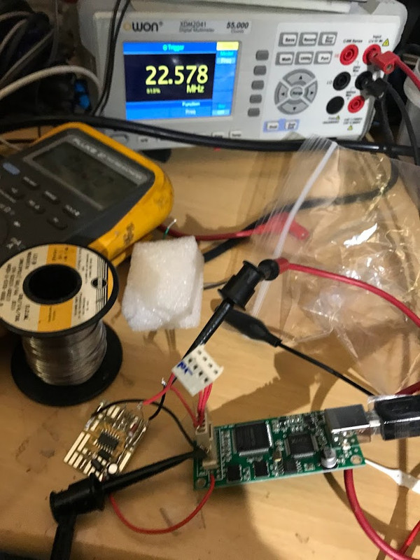
Almost there! Tested the Napier EDN /2 with a Vanguard 11.289 MHZ (5v common psu for both /2 and osc). Working as it was supposed to (properly dividing by 2).
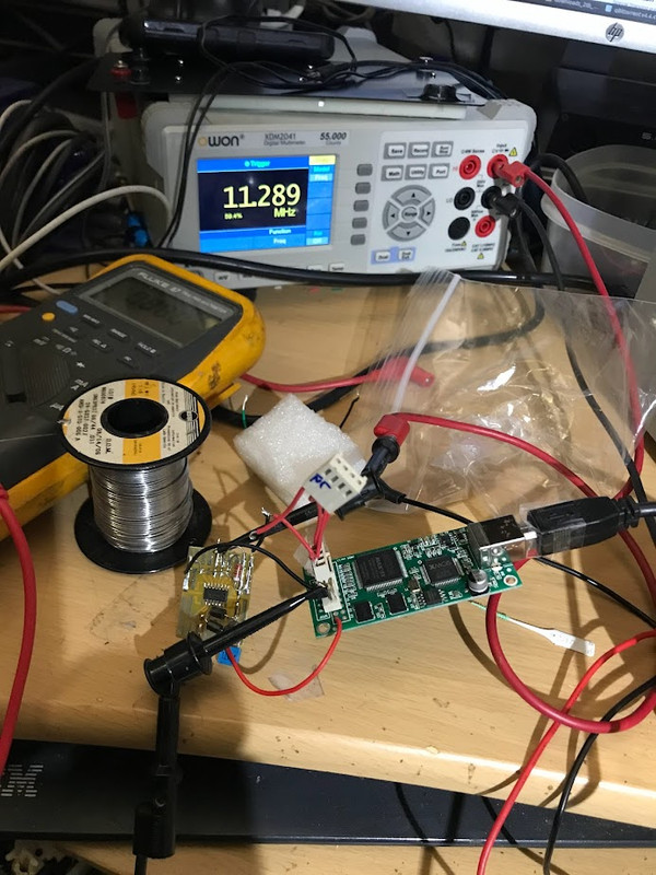
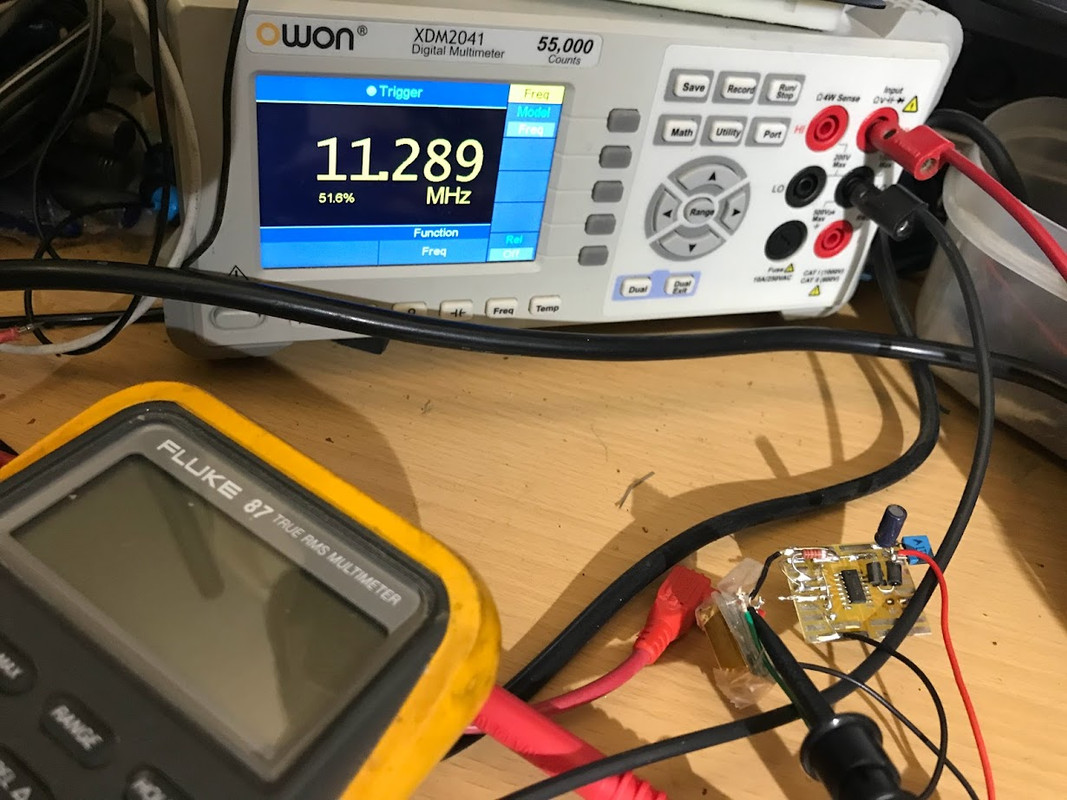
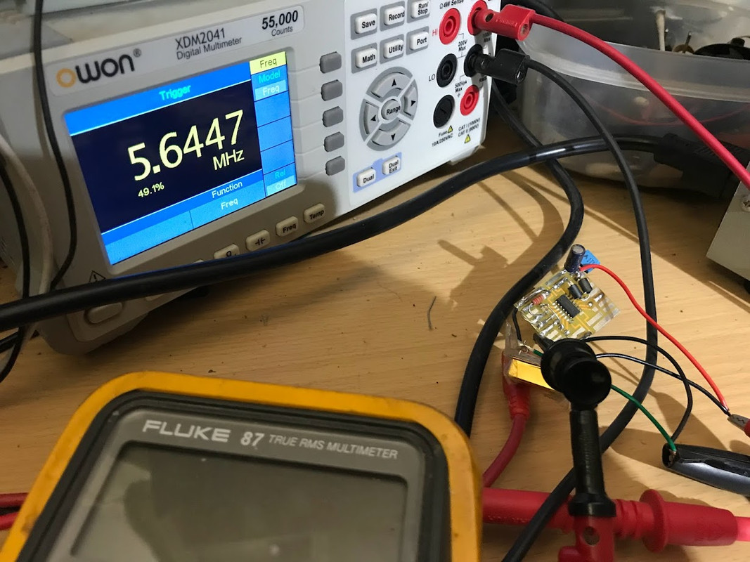
Then with USB-I2S adapter, but with the same 5v psu as on the Chinese 1305 board. All was not well ... weird output "/2" freq around 9.xx Mhz and fluctuating/unstable (input freq to /2 was normal at 22.578Mhz). Something not right; I suspected some sort of grounding issue.
Then I remembered "Would also recommend designing a small board with a ground plane and a local 3.3v regulator."
Not sure what you meant -- a dedicated 2.3 v. psu board?
IAC, the USB-I2s adapter has its own 3.3v power via thru-hole.
I removed both the adapter and /2 from the Chinese board.
Using only the adapter for power (3.3v), the /2 is working normally. See photos.
But having the adapter powering the /2 is not quite ideal although I have gone to some lengths to decouple the pwr input (caps and ferrite).
Also recall using low R's in the mck and I2S lines in prev. projects. Older Arcam and Cambridge CDPs used to "interfere" with the I2S lines that way , IIRC.
So that may be a further tweak.
I still have to test the adapter and /2 in the Chinese 1305 kit with music. Tomorrow, perhaps.
It's tomorrow. The /2 with the Chinese 1305 does not work -- no audio, just static -- even though freq. counter displays the correct (11.289 or 256fs) freq that the tda1305 requires per it's datasheet I2S specs.I still have to test the adapter and /2 in the Chinese 1305 kit with music. Tomorrow, perhaps.
Curiously, injection of an 11.289 osc (Vanguard) into MCK, as noted in the Naim thread, did yield some audio (but distorted).
I have built and successfully used the very same EDN /2 on several past projects, but all for older CDPs that use 11.289 osc.
Not sure what the problem is with the 1305 kit ??? ... e.g., synching to BCK/DATA/WS, etc.
Maybe /2 from 11.289 to 5.644 (which works in other CDPs), is slow enough for the glue logic to track in phase????
Dunno ??!!
One of these days, I'll have to rig up a test on my dual-ch 'scope.
I have this "high-rated" adapter on order:
https://www.ebay.com/itm/274101835307
Made by XING Digital ???
It's eBay product description does note: ". The MCLK output frequency can be individually configured for any format. From 64Fs to 512FS, from 2.8224MHZ to 49.152MHz, let the DAC chip exert excellent performance."
Hopefully this means a more straightforward solution.
Weird that the MCK rate is so neglected in Ali/ebay descriptions. Like it's some sort of solution you are expected to DREAM UP 😉
But how do I get my existing xmos to do that?The old Xmos XS1-L1 will do 256Fs, if you can find one.
Probably with difficulty. It doesn't have the XTAG header for loading different firmware that the L1 has though other options are available. I suppose the CPLD can be reconfigured but that might be a bit OTT. Interesting though, might be worth doing just for the sake of doing it.
If CPU on this board does not have Security Key burned in it's OTP area, and also JTAG is not switched off there....Otherwise there is at least one USB board on the market with a JTAG connector that you re-flash with firmware using XMOS software tools
Modern too - any XMOS will do this, also 512 or 1024 - it is just one "#define" in a source code.The old Xmos XS1-L1 will do 256Fs,
But one can understand that bclk frequency is <= mclk frequency, so with 256fs and 64bit/sample, the maximum sample rate will be 192kHz.
Maybe I did not clearly understand the problem, but is DAC required 256fs and XMOS 512fs, why not to put one sot32 chip (SN47LVC80, for example), to divide the clock frequency from 512 to 256 and close the issue? Instead of dealing with XMOS programming....
Diyinhk used to sell a USB board with an unlocked XMOS chip and holes for a JTAG connector. It was intended to be reprogrammable by an advanced user. Didn't see it recently on their website though. Still have one here that I never got around to messing with 🙂
do it out of the box.
What does it mean "out of the box"?
If you mean new chip, it do nothing, it's OTP is clear, just primary bootloader inside.
And the program (firmware) should be placed at external EEPROM. And if it encrypted, security key must be set at OTP.
I use L1 even now, and set MCLK frequency whatever I want - usually 512, but at some devices - 1024 (256 was never needed).
- Home
- Source & Line
- Digital Line Level
- XMOS XU208 Or Amanero USB