"New" XMOS (L1) does not have "jumpers and default settings", until you put it into PCB with external EEPROM chip, and burn a firmware.Out of the box means the default settings when newly received like options selected by jumpers.
It is just CPU.
XU208 - exactly the same
You may not be talking about the XMOS chip, but about a specific device.
Last edited:
Maybe not on planet Altor. Around here the XS1-L1 does. I am talking about boards in a thread about boards.
Last edited:
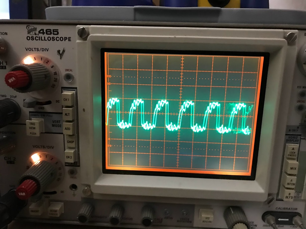
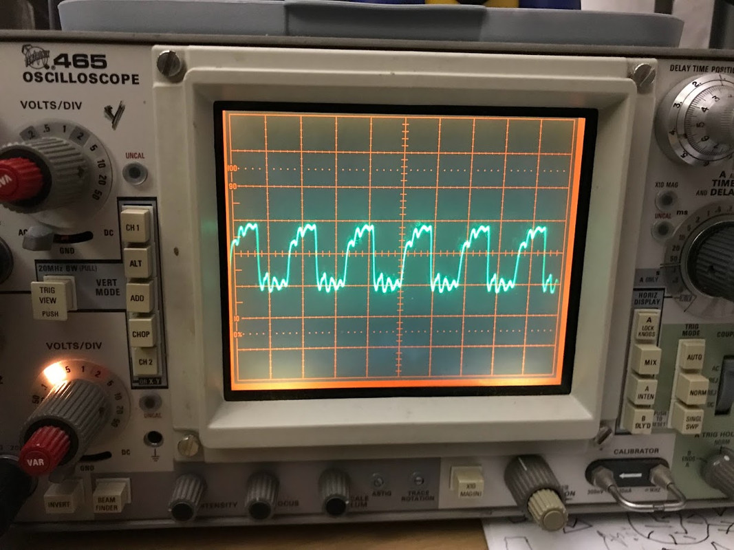
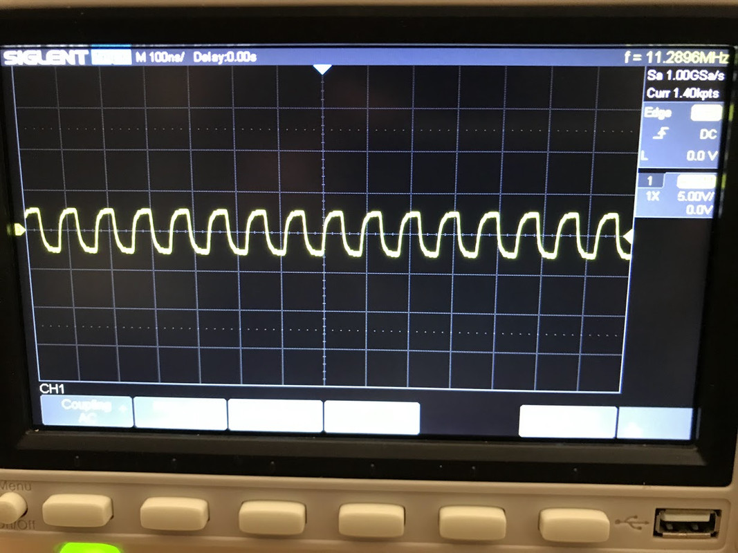
Some photos from my analog and digital 'scopes.
Images show BOTH input and output freqs.
Images captured and presented in different ways to get one to think outside the box -- maybe that will get the ol' noodle into the problem-solving mode 😉


Images show BOTH input and output freqs.
Images captured and presented in different ways to get one to think outside the box -- maybe that will get the ol' noodle into the problem-solving mode 😉
I use to write new firmware directly to the flash memory chip, since I don't have any Xmos JTAG programmer/debugger.
1. edit code and compile new firmare
2. use Xmos command line tool xflash to convert your_firmware.xe to your_firmware.bin
3. connect Xmos chip reset_n pin to GND for the IO pins to go on high impedance state, so you can make in circuit flash programming
4. programm SPI flash memory chip using an appropiate tool (I use Flashcat USB)
5. remember to set Q-bit to 1 if your flasch chip is connected in quad mode.
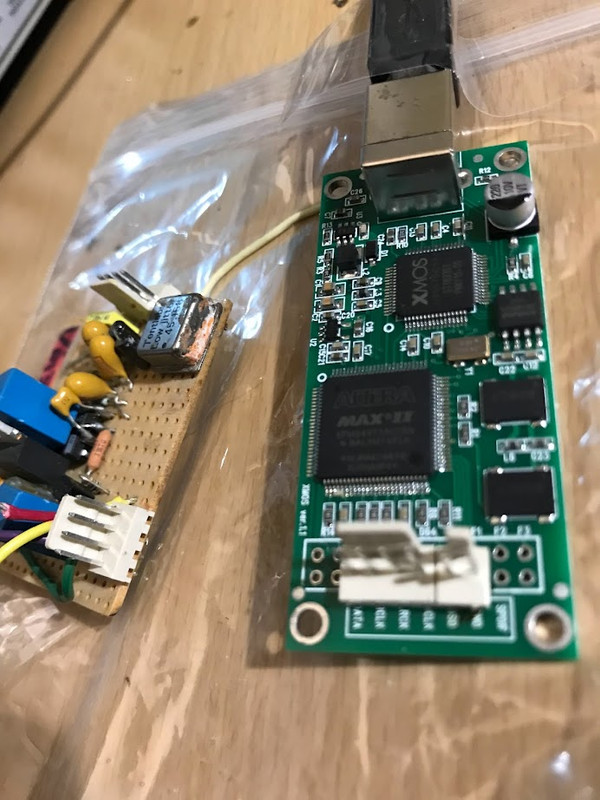
This is my board. (same photos from my Naim 1305 thread ) The one I can't get to work. It spits out MCK at 512fs. I need MCK output from this board to be 256fs. I don't know how to config/reprogram the board to spit out MCK=256fs. And the /2 physical ckt -- although both 'scope and freq. counter show 256fs (11.289 Mhz) -- yield only distorted audio.Maybe not on planet Altor. Around here the XS1-L1 does. I am talking about boards in a thread about boards.
Looks like both scopes probably have probe ground issues which is causing a lot of ringing. See if you can get spring grounds that fit your probes.Some photos from my analog and digital 'scopes.
Some information at: https://www.digikey.com/en/blog/why...probes-have-so-many-ground-connection-options
Also good info worth reading: https://download.tek.com/document/02_ABCs-of-Probes-Primer.pdf -->'Ground Lead Issues' section starts on page 46.

Yes, I wondered why that "ringing" is present. Or is it indeed ringing rather than the way the 'scopes do the math at this BW ?Looks like both scopes probably have probe ground issues which is causing a lot of ringing. See if you can get spring grounds that fit your probes.
The DAC datasheets do seem to show much cleaner (squarer) wave-forms.
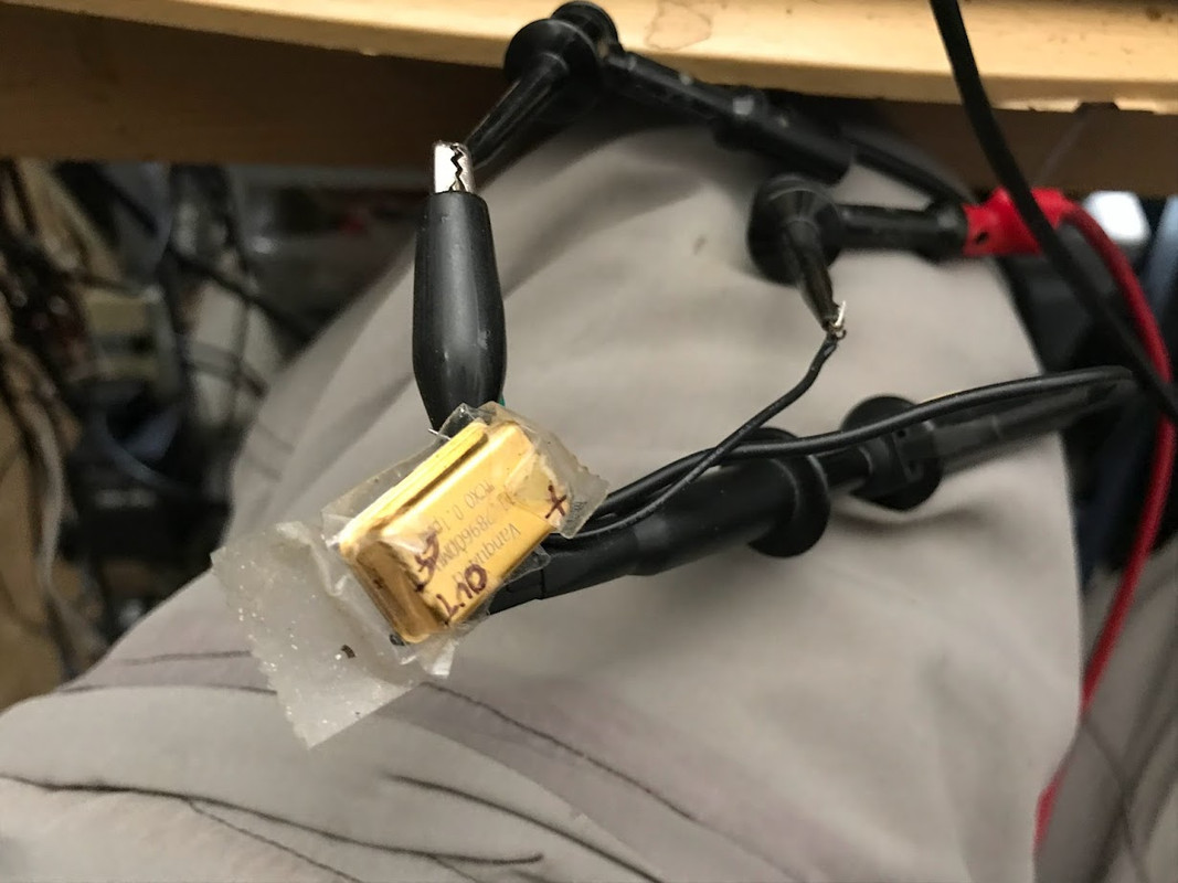
I use the alligator ground clip connected to probe.
Not sure spring would help (clean up the signal):
Also, I want to see (experience) what the DAC sees ("experiences"). So not sure a cleaner 'scope experience would be depicted with short/spring ground.
If you have pictures of your own 'scope shots, or your probing setup, that'd help 😉
About XMOS.
I contacted them directly and they emailed me this reply:
My query:
Query: I have a USB-I2s adapter that is outputting MCK = 512fs. How does one get an XMOS 208 device to output 256fs (MCK)?
I contacted them directly and they emailed me this reply:
My query:
Query: I have a USB-I2s adapter that is outputting MCK = 512fs. How does one get an XMOS 208 device to output 256fs (MCK)?
Thanks for reaching out to XMOS.
The procedure can be found in the USB Audio user guide here:
https://www.xmos.ai/download/sw_usb_audio:-sw_usb_audio-[user-guide](6.15.2rc1).pdf
Ignore the hardware section referencing the Multichannel Audio board and concentrate on the software section explaining the programming of the xcore200 device.
Thanks,
Nial
Nial Van Wagner
Americas Sales Director
XMOS Ltd.
Mobile: +1-408-421-6019
Yes. It is caused by the capacitance of the probe tip and inductance of the long ground lead. Together they form a tuned circuit that will ring when hit with a fast clock edge. The first solution is to make the ground lead inductance much less. A spring ground is very short and has very low inductance. If that's not enough, and sometimes it isn't then you need a low capacitance active probe too....is it indeed ringing...?
Right, but even if one uses spring clips and low-capacitance probes, we really don't know what the DAC at pins are experiencing (phenomenology).A spring ground is very short and has very low inductance. If that's not enough, and sometimes it isn't then you need a low capacitance active probe too.
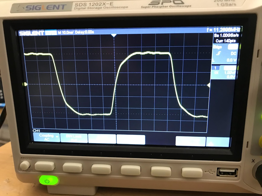
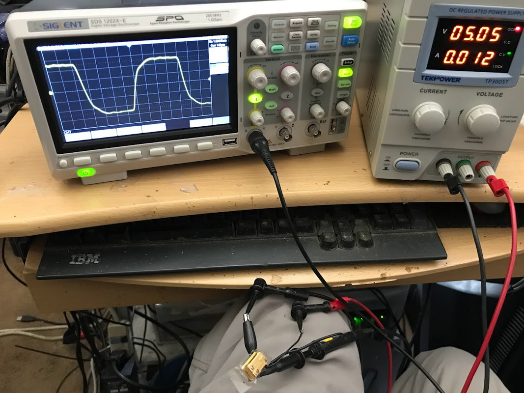
Both the old analog Tek 465 and the Siglent DSD digital scopes are showing the "ringing". So that may be what the MCK looks like regardless of improved probes and spring (see video in last post).
Scopes need to be out-of-the-box plug-n-play. So the need for elaborate probes - - especially below, say, 50 Mhz -- is a bit counterproductive.
See segment here (same Siglent model as mine):
All that said, the phenomena is curious ... hmmm ... I'll have to dig out my 11.289 Vanguard osc again. Stay tuned!
EDIT:
Got the Vanguard -- same probe setup as used w/adapter - - looks pretty clean ... and different from MCK of adapter. Yes?
Last edited:
Like it has already been stated, to do that you need to load new, custom XMOS firmware into your 208.About XMOS.
I contacted them directly and they emailed me this reply:
My query:
Query: I have a USB-I2s adapter that is outputting MCK = 512fs. How does one get an XMOS 208 device to output 256fs (MCK)?
It is not a trivial task.
You will need to adapt XMOS' multichannel audio sample project (written for the 216) to your 208 chip with its specific pinout.
Plus of course you will need to use clocks that correspond to 256fs (11.289 & 12.288MHz).
The 208 will not divide down your MCLK (sourced directly from your oscillators) for you.
The reasons are already very well understood technically. Whether or not you will see ringing depends on the resonant frequency of your probe and ground lead combination, and the rise/fall times of the square wave. If a clock edge changes fast enough (dv/dt) then it will contain frequency energy at the probe resonance. A slower clock edge may not change change fast enough to 'excite' the probe resonance. It is also well known that going to a spring ground can be expected to make a pretty substantial reduction in ringing. This is very old, very well understood physics. No mystery at all.Both the old analog Tek 465 and the Siglent DSD digital scopes are showing the "ringing".
Also, the clock signal almost certain look much better if measured properly. Scope and probe bandwidth should be at least 3 to 5 times higher than the clock frequency too. With a 200MHz you should be able to measure clock waveform fairly well for clock frequencies up to around 25MHz or 50Mhz, but not higher. Just get a some spring grounds that fit your probes and you can see for yourself.
How about a step-by-step procedure for us rookies 😉 ?Like it has already been stated, to do that you need to load new, custom XMOS firmware into your 208.
It is not a trivial task.
You will need to adapt XMOS' multichannel audio sample project (written for the 216) to your 208 chip with its specific pinout.
Plus of course you will need to use clocks that correspond to 256fs (11.289 & 12.288MHz).
The 208 will not divide down your MCLK (sourced directly from your oscillators) for you.
Wanna volunteer?
Or should I ask XMOS? They are the seller, I am the customer. So I get be obligated, yes?
Is it just the 208 model that's the limiting factor? Or modern XMOS chips themselves?The 208 will not divide down your MCLK (sourced directly from your oscillators) for you.
As I mentioned earlier, and as I've JUST come to notice, most of kit dac boards say nothing about the MCLK rate in their ebay/Ali description. Offering an variable (end-user-electable rate) be so non-trivial that few invest in offering it.
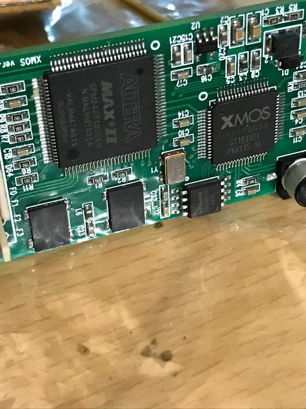
Often there may be a CPLD chip and an XMOS chip. IIRC the XMOS chip is sort of parallel processing CPU type of thing, but with a unique hardware feature architecture. A CPLD is programmable logic device that is more like using discrete logic chips. There is a 'Hardware Description Language' (HDL) to configure the logic. A clock divider might be implemented in the CPLD chip.
https://www.xmos.ai/download/xCORE-Architecture-Flyer(1.3).pdf
https://en.wikipedia.org/wiki/Hardware_description_language
Or you could use a dedicated clock divider chip like I did, or some other discrete logic implementation. Whatever solves your problem, right?
https://www.xmos.ai/download/xCORE-Architecture-Flyer(1.3).pdf
https://en.wikipedia.org/wiki/Hardware_description_language
Or you could use a dedicated clock divider chip like I did, or some other discrete logic implementation. Whatever solves your problem, right?
It spits out MCK at 512fs. I need MCK output from this board to be 256fs. I don't know how to config/reprogram the board to spit out MCK=256fs.
I said before - why you need to reprogram the board, if one 50-cent sot23 chip may solve this problem in 5 minutes?
Moreover, the result will be much better.
Last edited:
Someone again confuses the device and the chip!Is it just the 208 model that's the limiting factor? Or modern XMOS chips themselves?
The "limiting factor" is the existing program on specific board.
XMOS chips themselves do not have this limitation, neither 208, nor modern, nor old L1.
What else can I say - do not use a master clock for sigma-deltha DACs, (or LRCLK/Latch for old parallel DACs) coming directly from the processor or FPGA. You won't be happy with jitter.
P.S. I've been making my stereo and multichannel boards with different XMOS using my own firmware for almost 10 years.
altor: Both of your above two replies are confusing to me. Talk to me like I'm a student in a "101" class. I am using a TDA1305 dac which requires 256fs MCK input. Can't be higher for I2S. And I can't use a dedicated osc/clock (11.289 mhz) -- it must be 256fs (11.289 mhz) generated by the same device as the three I2S lines. Please be more specific about what your 5-minute solution with an sot23 chip specifically means? Name the sot23 device and describe or provide a ckt.
Markw4: "Or you could use a dedicated clock divider chip like I did, or some other discrete logic implementation". As I noted in post 50, I did try that. The correct freq. -- 11.289 Mhz (256 fs) -- spat out but w/ distorted sound. Something to do with synch, I suppose.
Markw4: "Or you could use a dedicated clock divider chip like I did, or some other discrete logic implementation". As I noted in post 50, I did try that. The correct freq. -- 11.289 Mhz (256 fs) -- spat out but w/ distorted sound. Something to do with synch, I suppose.
Last edited:
Altor probably meant single flip-flop 74LVC1G80 to divide by 2 the MCK coming from the XMOS board. If this does not work as you've mentioned I would check that the XMOS board is configured for I2S output instead of MSB/LSB. Have you verified that your XMOS board works with some other DAC?
- Home
- Source & Line
- Digital Line Level
- XMOS XU208 Or Amanero USB